


Nomenclatures
${{\omega }_{n}}$---The natural frequency of the system
$\zeta $---The damping ratio
${{V}_{0}}$---The initial speed of the recoil structure
$G(t)$---The impact force
$\sigma $---The displacement limit
$k$--- The stiffness
$c$--- The damping coefficient
${{\omega }_{d}}$---The frequency of system attenuation vibration
$\left| {{x}_{w}} \right|$---The absolute value of system steady-state displacement
${{X}_{peak}}$---The maximum recoil displacement
${{t}_{w}}$---The steady-state time
${{\sigma }_{peak}}$---The maximum steady-state displacement
${{Q}_{1}}$---The maximum acceleration
${{Q}_{2}}$---The maximum steady-state displacement
${{Q}_{3}}$---The maximum recoil displacement
1. Introduction
Overhead weapon station (OWS) is a modular weapon system that can be equipped on multiple platforms, reduce weapon system response time, and solve the problem that operators normally do not have armor protection[1]. However, the existing weapon station commonly yields poor accuracy and dispersion, due to insufficient the damping effect provided by the recoil-attenuating device that connects the gun body and the mounting structure. Therefore, such a device is incapable of dissipating the great energy generated when the gun fires.
According to the artillery recoil device design experience, damping elements to the device can absorb recoil energy, reducing muzzle vibration. The goal of weapon station researchers isto design a new recoil-attenuating device including damping elements to improve the existing spring buffer.
Nowadays, the fast development of new buffer material, such as magneto-rheological fluid[2-3], electro-rheological fluid[4], compressible fluid[5], rubber composites[6], polymers[7-8], air spring[9], and metal rubber[10], provides a new way of designing a new recoil-attenuating device. Hence, these are used at home and abroad to control the launch of artillery and automatic weapons. For example, Ahmadian et al.[11-12] attempted to use a magneto rheological damping control system in a gun recoil system andshowed that using the magneto rheological damper can control the regularity of recoil. Patil et al.[13] used a high yield strength electro-rheological fluid (ER) to design a semi-active smart recoil system for artillery guns that can improve emissivity and firing accuracy by adjusting the damping force. Chen[14] applied an elastomer buffer to the artillery recoil reducer, established an impact environmental mechanics model suitable for the elastomer buffer, and systematically studied the time-varying characteristics of the damping parameters of the elastomer buffer. Regardless of which cushioning material or combination of cushioning media is chosen, the modification of spring stiffness, damping coefficient, and damping ratio of the cushioning device is essentially involved.
Hence, based on the real-world operating requirements of the overhead weapon station, an optimal design model of the buffer device with multi-indices constraints is established in this paper. This model is used to obtain the optimal buffer device parameters and lay the ground for the future development of recoil-attenuating devices.
2. Design Specifications for the Recoil-Attenuating Device with Damping
The buffer device of the overhead weapon station is fixed to a cradle, which can absorb and release energy through deformation. The damping component within the device can dissipate part of the recoil energy, reducing the impact of the shooting load on the mounting system and thus attenuating the effect of the impact response on muzzle vibration, the sighting device, and the stabilizing system, which leads to better dispersion. The overhead weapon station usually takes automatic-firing as the main operating condition and requires the recoil part to be reset to the initial steady position in a very short time to reduce the initial disturbance when firing the next round. Meanwhile, the continuous feeding system also requires the maximum displacement of recoil to be strictly controlled within a certain range. Therefore, the design of a damping buffer device should meet the following three requirements.
2.1. Maximum Acceleration
Lightweight design of overhead weapons station requires that the dimensions of the mounting system (cradle, bracket), pitch/orientation motor size, motor power, maximum motor torque, and impact force transmitted to the mounting system are within a limit. The physical contact between components caused by the impact load and the elastic deformation of the mounting system are the most important factors that cause the muzzle vibration. In order to maintain good firing accuracy, the maximum impact force cannot be kept below a threshold. In an overhead weapon system, the sighting device is coaxially connected with the trunnion. A large impact force will cause the sight line to vibrate, affecting sighting accuracy. In the worst-case scenario, the sight sighting device can evenbe damaged. Therefore, the damping buffer device should be able to limit the maximum impact force, in order to meet the requirements of the permissible impact load of the mounting system and the sighting device.
The motion of an over-head weapon system with damping during recoiling is governed by the following differential equations:
The natural frequency of the system is ${{\omega }_{n}}=\sqrt{K/M}$, and the damping ratio is $\zeta =C/(2\sqrt{KM})=C/(2M{{\omega }_{n}})$. Thus, the above equation can be expressed as:
Reference [15] indicates that the velocity step technique can be used to simplify the calculation of the system impact response. Therefore, the initial speed of the recoil structure (${{V}_{0}}$) is assumed to be equal to the maximum velocity produced after firing (${{v}_{\max }}$). In other words, ${{V}_{0}}$≈${{v}_{\max }}$. Assuming that $x(t)=X(t)/{{v}_{\max }}$, Equation (2) can be further written as:
Figure 1 provides a free-body diagram that describes the motion of the recoil structure. The impact force is defined as:
Figure 1.
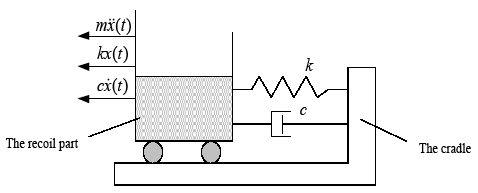
Figure 1.
Free-body diagram of an overhead weapons station
According to the maximum impact requirements, $G(t)=m\ddot{x}(t)$ should be less than a certain threshold. Considering the mass of the recoil part m is a constant value, the maximum acceleration is used to meet the maximum impact requirements. The definition of the maximum acceleration of a damping buffer device is:
2.2. Maximum Steady-State Displacement
In order to ensure the firing dispersion, an overhead weapon station is required to have better launch stability, including blowback and counter-recoil stability. In order to make sure that the recoil part can reset to the equilibrium position quickly during continuous firing, the damping buffer device needs to have quick reset.
According to the concept of steady-state displacement in [16], the steady-state displacement can be used to indicate how fast a reset process is. Therefore, the steady-state displacement in this study is defined such that: After time${{t}_{w}}$, the maximum displacement of the system is less than the displacement limit $\sigma $, that is, the system is stable at this time. However, after time ${{t}_{w}}$, the maximum displacement is the maximum steady-state displacement. Thus, the definition of the maximum steady-state displacement indicators of the damping buffer device is:
2.3. Maximum Recoil Displacement
The ammunition box of the overhead weapon station is connected to an auto-feeding mechanism by the rotary hard guidance and the flexible guidance. The excessively large recoil displacement can easily lead to poor feeding in automatic-firing. As a result, the recoil displacement must be within a certain range. Namely, the maximum displacement of the damping buffer device is less than the maximum allowable displacement of the recoil displacement. Therefore, the definition of the maximum recoil displacement of the damping buffer device is:
For a recoil-attenuating device with determined initial parameters, ${{Q}_{1}}$, ${{Q}_{2}}$, ${{Q}_{3}}$are functions of the natural frequency ${{\omega }_{n}}$ and damping ratio $\zeta $. The system stiffness $k$ and damping coefficient $c$ can therefore be determined based on the natural frequency and damping ratio. Hence, the design of the damping buffer device is turned into an optimization problem to minimize the effect of the maximum acceleration ${{Q}_{1}}$ on the steady-state displacement ${{Q}_{2}}$ and the maximum recoil displacement ${{Q}_{3}}$. The optimization model can be expressed as:
3. Impact Response Solution
The kinematic differential Equations (3) can be used to solve the acceleration response, steady-state displacement response, and recoil displacement response of the buffer system with different damping ratios. In this paper, only the response of small damping ratio $(0\le \zeta 1)$is considered, and the critical damping and over damping are not analyzed.
3.1. Acceleration Response Solution
The system acceleration response can be obtained from Equation (3) [17]:
Where ${{\omega }_{d}}={{\omega }_{n}}\sqrt{1-{{\zeta }^{2}}}$ is the frequency of system attenuation vibration.
Differentiating Equation (9) and setting the time derivative equal to zero, we can determine when the maximum acceleration response happens, which gives:
Since the maximum absolute value of the system acceleration response only occurs at t=0s or at the first extremum, which is affected by the phase, the time of the first extremum of the acceleration response depends on the magnitude of the damping ratio $\zeta $:
Substituting Equation (11) into Equation (9) yields the absolute value of the first extremum of the system acceleration response, which is:
Substituting $t=0$ into Equation(9) yields the absolute value of the acceleration response of the system at the beginning, which is:
Figure 2 shows the relationship between the maximum acceleration response absolute value at the zero moment and the first extremum moment with the damping ratio.
Figure 2.
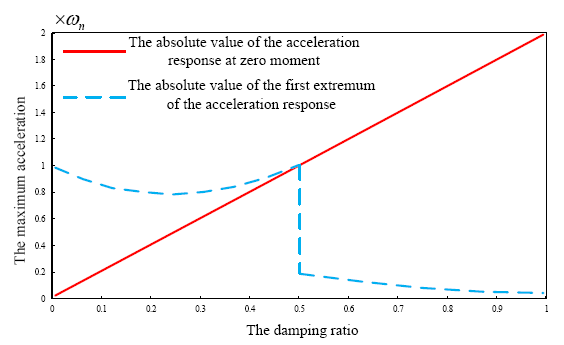
Figure 2.
The relationship between the absolute maximum acceleration response and damping ratio
Figure 2 shows that, when $0\le \zeta \le 0.5$, the absolute value of the acceleration response at the first extremum moment is greater than the acceleration at zero moment. In this case, the absolute value of the maximum acceleration response is ${{\left| \ddot{x}({{t}_{a}}) \right|}_{\max }}$. However, when $0.5\zeta 1$, the acceleration at time zero is greater than the absolute value of the acceleration response at the first extremum. In this case, the absolute value of the maximum acceleration response is $\left| \ddot{x}(0) \right|$.
In summary, the maximum value of the absolute value of the system acceleration response can be expressed as:
3.2. Steady-State Displacement Response Solution
Figure 3.
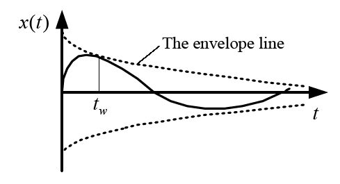
Figure 3.
The time history of displacement response
In Figure 3, it can be seen that the envelope line function of the displacement response can be used to represent the steady-state displacement. The envelope line function equation is:
The absolute value of system steady-state displacement is:
3.3. Recoil Displacement Response Solution
According to Equation (3), the system displacement response can be derived as:
Differentiating Equation (17) and setting the time derivative equal to zero, we can determine when the maximum displacement response happens, which gives:
Since the displacement of the system at the beginning is zero, the time of the maximum value of the absolute value of the system displacement response is:
Substituting Equation (19) into Equation(17), the maximum value of the absolute value of the recoil displacement response can be obtained:
4. Parameter Optimization of Damping Buffer Device with Triple-Index Constraints
According to the range of different damping ratios, the optimization problem can be described by Equation (8):
When $0\le \zeta \le 0.5$, the parameter optimization problems can be expressed as:
When $0.5\zeta 1$,the parameter optimization problems can be expressed as:
If the maximum recoil displacement ${{X}_{peak}}$, the steady-state time ${{t}_{w}}$, and the maximum steady-state displacement ${{\sigma }_{peak}}$are provided, the minimum acceleration response ${{Q}_{1}}$ can be obtained based on Equations (21) and (22). Thus, the ${{\omega }_{n}}$ and $\zeta $of the response are then determined to meet the design specifications for the natural frequency and damping ratio of the damping buffer device system accordingly. Lastly, the stiffness coefficient $k$ and damping coefficient $c$ of the system can be obtained.
It can be seen from the solution of the shock response in the previous section that there are contradictions in the selection of each parameter. The designed damping buffer device needs to meet three response requirements at the same time. However, the process of iterative solution using the conventional traversing method is not concise and effective. Thus, the following section discusses determining two parametersfirst, and then optimizingthe another one.
4.1. $\zeta$ Solution at Maximum Acceleration and Recoil Displacement
Multiplying Equation (14) by Equation (20) yields:
The constraint equation for the buffer system at maximum acceleration and recoil and its function curve are given in Equation (23) andFigure 4, respectively.
Figure 4.
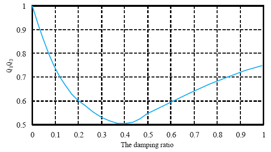
Figure 4.
The relationship between the acceleration and recoil displacement are constrained by damping ratio
It can be seen from Figure 4 that an optimal ${{\zeta }_{opt}}$, which is below 0.5, can be obtained at the maximum acceleration and recoil displacement. Furthermore, the value of ${{\zeta }_{opt}}$ is 0.404 based on Equation(21) when setting the derivative to zero. Note that ${{\zeta }_{opt}}$ is calculated considering the requirements for ${{Q}_{1}}$ and ${{Q}_{3}}$ only.The approach on how to satisfy the requirements for all three indexes will be provided in the next section.
4.2. Analysis of Relationship Between ${{Q}_{2}}$ and $\zeta $ at the Maximum Recoil Displacement
As shown in Equation (16) and Equation (20),there are no analytical expressions to derive ${{Q}_{2}}$ and ${{Q}_{3}}$. The curve of recoil displacement constraint ${{Q}_{2}}$ will be changed with the change of the ${{Q}_{3}}$ value. The values of ${{\omega }_{n}}$ and $\zeta $will be changed when the values of ${{Q}_{2}}$ and ${{Q}_{3}}$ are fixed. If the maximum recoil displacement is given, the curve of the relationship between ${{Q}_{2}}$ and $\zeta $ can be obtainedby solving the optimization equation, which is shown in Figure 5.
Figure 5.
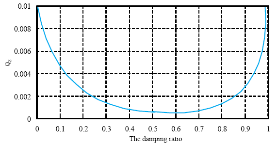
Figure 5.
The relationship between steady-state displacement and damping ratio
As can be seen from Figure 5, it is possible for each steady-state displacement to obtain an effective damping ratio (at the minimum) at the maximum recoil displacement constraint, and it is also possible to obtain both damping ratios simultaneously. Therefore, the relationship between the other two indicators should be considered as well before making the choice.
4.3. Characteristic Parameters Solution at Constant Values of Three Indexes
Based on the analysis above, the process of solving the minimum acceleration index ${{Q}_{1}}$ at the maximum steady-state displacement index ${{Q}_{2}}$ and the maximum recoil displacement index ${{Q}_{3}}$ can be described as follows:
The range of $\zeta $ can be determined according to the given maximum steady-state displacement index${{Q}_{2}}$, while assuming the range of damping ratio (a, b).
The damping ratio at minimum acceleration response is then determined according to the values of $a$ and $b.$ As can be seen from Figure 2: when b is below 0.404, the minimum acceleration response ${{Q}_{1}}$ is obtained at the point $\zeta =b;$ when a is over 0.404, the minimum acceleration response ${{Q}_{1}}$is obtained at the point $\zeta =a;$ however, when $a\le 0.404\le b,$the minimum acceleration response ${{Q}_{1}}$ is obtained at the point $\zeta =0.404.$ Thus, the optimal damping ratio can be expressed as:
The natural frequency ${{\omega }_{n}}$ can be obtainedby introducing the optimal damping ratio ${{\zeta }_{opt}}$ into Equation (20). Assuming the maximum recoil displacement index is ${{X}_{peak}}$, then the natural frequency of the buffer system can be expressed as:
According to the first two steps to obtain ${{\omega }_{n}}$ and ${{\zeta }_{opt}}$, the optimal stiffness coefficient ${{k}_{opt}}$ and the optimal damping coefficient ${{c}_{opt}}$ can be obtained based on ${{\omega }_{n}}$ and ${{\zeta }_{opt}}$ in the first two steps.
These equations are derived and solved after normalization, so the step speed ${{V}_{0}}$ needs to be multiplied into those equations during the actual calculation. According to the law of momentum conservation, ${{V}_{0}}={{m}_{d}}{{v}_{0}}/{{m}_{hz}}$, where ${{m}_{d}}$ is the bullet mass, ${{v}_{0}}$ is the muzzle velocity of the bullet, and ${{m}_{hz}}$ is themass of the recoil portion.
5. Calculation and Analysis of Characteristic Parameters of Damping Buffer Device
In the existing program of the overhead 30-gun weapon station, the maximum recoil impact, maximum recoil displacement, and stable time are 48000N, 24.5mm, and 200ms, respectively. Firstly, the operation of this system will be more stable when the maximum recoil impact is reduced to below 40000N, according to the driving motor power, the requirements of the mounting system, and the viewing device for the permissible impact load. Secondly, the maximum firing rate of the overhead weapon station is 400rounds/min. In order to ensure that the recoil part can be quickly reset to the equilibrium position under automatic-firing condition, the stable time needs to be decreased to 150ms. This stable time is beneficial for improving the shooting accuracy. Besides, the existing feed mechanism limits the recoil displacement to 30mm. Thus, the maximum recoil displacement of the damping buffer device is set to 30mm.
In summary, the constraints of the damping buffer device at the overhead weapon station are as follows:
$\cdot$ the maximum recoil impact is less than 40000N;
$\cdot$ the stable time is less than 150ms;
$\cdot$ the maximum steady-state displacement is 2mm;
$\cdot$ the maximum recoil displacement is less than 30mm.
Some parameters of overhead weapon station are as follows: the mass of recoilpart ${{m}_{hz}}=282\text{kg}$, the bullet mass ${{m}_{d}}=0.48\text{kg}$, and the muzzle velocity of the bullet ${{v}_{0}}=935\text{m/s}$. Then, substituting initial values and constraints above into the parameter optimization formula in the previous section, the optimal damping ratio can be obtained as ${{\zeta }_{opt}}=0.607$. The ${{\omega }_{n}}=52.6\text{rad/s}$ can be obtained by substituting ${{\zeta }_{opt}}$ into Equation (20). Moreover, the equations in this section are derived after normalization; hence, the calculation values need to be multiplied by the velocity step value ${{V}_{0}}={{m}_{d}}{{v}_{0}}/{{m}_{hz}}=1.6\text{m/s}$. $k=780\text{N/mm}$and$c=18\text{N}\cdot \text{s/mm}$ can be obtained based on ${{\zeta }_{opt}}$ and ${{\omega }_{n}}$.
In order to verify the effectiveness of the designed damping buffer device, $k$ and $c$ for the spring damping bumper are defined according to the design value in the rigid-flexible coupled dynamic model of the constructed overhead weapon station (as shown in Figure 6). Since two same springs are symmetrically arranged on both sides, the $k$ and $c$ values of the dynamic characteristics simulation are half of their theoretical values. Figure 7(a) and Figure 7(b) show the deformation curve and force curve of the damping buffer under the shooting condition. It can be seen that the maximum recoil force of the unilateral damping buffer received is 19852N. The maximum impact force of the recoil part is two times larger, which is less than 40000N. It meets the requirements of the indicator. Also, the maximum recoil displacement is 26.21mm and the stable time is 146ms, which means that they all satisfy the design requirements.
Figure 6.
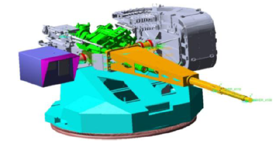
Figure 6.
Rigid-flexible coupled dynamic model of overhead weapon station
Figure 7.
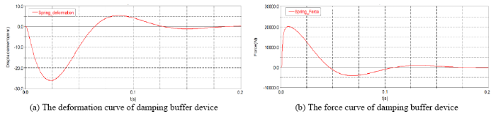
Figure 7.
The curve of the damping buffer under shooting condition
Figure 8 shows the acceleration at the centroid of the sights flange.It can be seen from the figure that the maximum impact acceleration of the sight device is reduced from 3014m/s2 to 2257m/s2, which is 25.12%, after using the damping buffer device. The damping buffer device can effectively reduce the impact of the shooting load on the sighting device. Consequently, the sighting accuracy, tracking accuracy, and reliability of the sighting device during shooting can be further improved.
Figure 8.
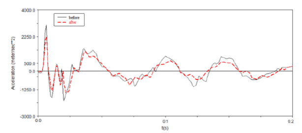
Figure 8.
The comparison of impact acceleration curve of sighting device with damping buffer device
Figure 9(a)-Figure 9(d) show the comparison of the vibration parameters of the muzzle before and after using the damping buffer device. It can be seen from these figures that the peak values of the linear velocity and the angular displacement of the muzzle at the moment the bullet leaves the muzzle all are decreased. The angular displacement is decreased. Moreover, due to the increased damping, the vibration attenuation is significantly accelerated.
Figure 9.
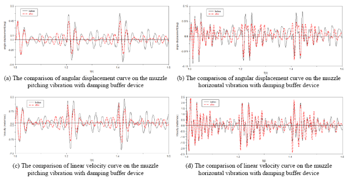
Figure 9.
The characteristics of muzzle vibration with damping buffer device
Table 1 shows the comparison of vibration parameters variance before and after using the damping buffer device at the moment the bullet leaves the muzzle. The dispersion variances are decreased after using the damping buffer device, among which the dispersion variance of pitching is reduced by 35.40% while the dispersion variance of horizontal is reduced by 30.77%.
Table 1. The comparison of vibration parameters variance with damping buffer device at the moment of bullet leaving the muzzle
| The variance of pitching angular displacement | The variance of horizontal angular displacement | The variance of pitching linear velocity | |
|---|---|---|---|
| Without | 0.000674 | 0.000073 | 0.066471 |
| With | 0.000467 | 0.000043 | 0.034728 |
| Change rate/% | 30.71 | 41.10 | 47.75 |
| The variance of horizontal linear velocity | The dispersion variance of pitching | The dispersion variance of horizontal | |
| Without | 0.010007 | 0.0113 | 0.0013 |
| With | 0.009139 | 0.0073 | 0.0009 |
| Change rate/% | 8.68 | 35.40 | 30.77 |
The damping buffer device on the overhead weapon station can greatly reduce the dispersion variance and therefore fundamentally reduce the recoil impact. This will also be beneficial for increasing the stability of the mounting system and the viewing device. Furthermore, the damping buffer device can be combined with the structural parameter optimization method in engineering practice. This approach will further improve the shooting accuracy and stability and promote the technology improvement for the overhead weapons station.
6. Conclusions
This paper proposed three indices to evaluate the performance of a recoil-attenuating device under real-world operating requirements, including the maximum acceleration, maximum steady-state displacement, and maximum recoil displacement. In addition, this paper also determined the system acceleration response, steady-state displacement response, and recoil displacement response with various damping ratios.
Through the optimization design analysis of the damping buffer device under the constraint of two indices, a method of solving the optimal buffer parameters under the constraint of three indices is proposed. Furthermore, the optimized stiffness of the damping buffer device is calculated ask=780N/mm and the optimized damping coefficient is calculated asc=18N·s/mm.
The optimized parameters of the damping buffer device are substituted into the model of an overhead weapon station for analysis. The results show that: (1) the maximum impact acceleration of the sighting device is reduced by 25.12%, which effectively reduces the recoil impact; (2) the dispersion variances of horizontal and pitching decreased by more than 30%, and thus the firing accuracy is greatly improved. In conclusion, the results can be used for the development of overhead weapon stations in the future.
Reference
“A Summary for Vehicular Overhead Weapon Stations,”
“Dynamic Sealing Using Magneto-Rheological Fluids,”
“A Review on Parametric Dynamic Models of Magnetorheological Dampers and Their Characterization Methods,”
“Rotating Shaft Damping with Electro-Rheological Fluid,”
“A Method for the Identification of Hydraulic Damper Characteristics from Steady Velocity Inputs,”
DOI:10.1016/j.ymssp.2010.05.021
URL
[Cited within: 1]

The research presented in this paper investigates the possibility of precise experimental identification of steady damper characteristics. The paper considers velocity sensitive and nominally symmetric hydraulic dampers. The proposed identification methodology is based on a piecewise constant velocity excitation. One goal of the paper is to analyze the transient nature of the damper response in the context of finite permissible piston displacements and first order transient effects due to elastic elements in the damper structure. The proposed methodology is formalized in a framework suitable for experimental design, allowing the detailed study of steady state damper performance. The second goal of the paper is to demonstrate the practical application of the proposed methodology. It is applied to the case of a safety critical hydraulic damper used for stability augmentation in production helicopters. The research work presented shows that this methodology can be used for identification in a finite but relatively wide range of piston velocities. The case study demonstrates a successful example of damper property identification where the resulting characteristics prove useful as a tool for model validation. Finally, the identification results are related to the results of a more traditional test with harmonic piston excitation.
“Viscoelastic Behaviour of Silica Filled Natural Rubber Composites-Correlation of Shear with Elongational Testing,”
“An Investigation on the Bound Rubber and Dynamic Mechanical Properties of Polystyrene Particles-Filled Elastomer,”
DOI:10.1002/pc.23673
URL
[Cited within: 1]
Polymeric nanoparticles have many advantages as the reinforcing filler of rubber. To investigate the mechanism of the reinforcement, nanocomposites of poly(styrene-butadiene) rubber (SBR) filled with polystyrene (PS) particles as the reinforcing agents was prepared. Morphology and dynamical mechanical properties of PS particles-filled SBR were investigated. It was found that the polymer chains of the elastomer could be absorbed onto the PS particles, in reminiscent to the concept of bound rubber in inorganic filler-filled elastomeric system. The adsorbed polymer layer can form up glassy bridges between neighboring filler particles, leading to the agglomeration of the filler particles and the reinforcement of the elastomer. With higher filler content or smaller filler size, the numbers of the glassy bridges increase, and the modulus of the elastomer increases. With higher strain or higher temperature, the filler iller interaction is disrupted and the material is softened. The study discovered the existence of bound rubber in PS particles-filled elastomer and illustrated its influence on the dynamic mechanical properties, which could be helpful to design the polymeric nanoparticles for rubber reinforcement. POLYM. COMPOS., 2015. 2015 Society of Plastics Engineers
“Effect of Chain Architecture of Polyol with Secondary Hydroxyl Group on Aggregation Structure and Mechanical Properties of Polyurethane Elastomer,”
DOI:10.1016/j.polymer.2017.03.031
URL
[Cited within: 1]
Polyurethane elastomers (PUEs) based on poly(2-ethyl-1,3-hexamethylene adipate) glycol (PEHA), poly(2,4-diethyl-1,5-pentamethylene adipate) glycol (PDEPA) and poly(2-butyl-2-ethyl-1,3-trimethylene adipate) glycol (PBETA) were synthesized with 4,4 -diphenylmethane diisocyanate (MDI) and 1,4-butane diol (BD)/1,1,1-trimethylol propane (TMP). PEHA has one primary and one secondary hydroxyl groups, but PDEPA or PBETA has two primary hydroxyl groups. The effect of low reactive secondary OH group on molecular aggregation structure and mechanical properties of the PUEs was investigated using Fourier transform infrared spectroscopy (FT-IR), differential scanning calorimetry (DSC), small-angle X-ray scattering (SAXS), dynamic viscoelastic measurement and tensile testing. The study demonstrates that PEHA-based PUE has lower cross-linking density and lower degree of microphase separation than PDEPA- and PBETA-based PUEs. As a result, PEHA-based PUE has lower dynamic storage modulus value at the rubbery plateau region and Young's modulus.
“A Novel Air Spring Dynamic Model with Pneumatic Thermodynamics, Effective Friction and Viscoelastic Damping,”
DOI:10.1016/j.jsv.2017.07.015
URL
[Cited within: 1]
An accurate air spring model is critical for vehicle design equipped with air spring pneumatic systems to provide a better performance. However, it is particularly difficult to establish a generalized analytical model to predict the amplitude- and frequency-dependent behaviors of an air spring resulting from many factors such as thermodynamics, friction, and damping. In this paper, an air spring dynamic model is developed by considering the thermodynamics of the bellow-pipe-tank pneumatic system, the effective friction, and viscoelastic damping of the bellow rubber. It is worth mentioning that parameters in the friction model depend on the standard deviation of the displacement excitation through a statistics method rather than constant values in the classic Berg's friction model. The bellow rubber viscoelastic property is modeled by a fractional calculus element with only two parameters. The proposed model parameters are identified and further validated by conducting bench tests of the stand-alone air spring component and the bellow-pipe-tank system, separately. Several models for the air spring are compared with the proposed model and the measurements in harmonic excitations with different amplitudes and frequencies, and random excitations with both large and small displacement cases. The results of comparison show that the proposed model can accurately predict the dynamic characteristics of the air spring in an acceptable computation time.
“An Analytical Study of Fire Out of Battery Using Magneto-Rheological Dampers,”
DOI:10.1155/2002/983140
URL
[Cited within: 1]
The application of magneto rheological dampers for controlling the dynamics of a fire out-of-battery recoil system is examined, using a dynamic simulation of a 105mm cannon. Upon providing a brief background on MR dampers and fire out-of-battery dynamics, we will describe the simulation model, along with some of the results obtained from the model. The simulation results show that although conventional hydraulic recoil dampers can be designed and tuned to control fire out-of-battery dynamics as effectively as MR dampers, they are not able to perform well when firing faults are encountered. The results show that MR dampers are able to adapt to the firing faults such as pre-fire, hang-fire, and misfire and provide "soft recoil" under all firing conditions. The inability of conventional hydraulic dampers to adapt to the firing faults can yield recoil dynamics that seriously jeopardize the performance of the gun. Therefore, the results presented here show that MR dampers may provide an enabling technology in achieving fire out-of-battery under all firing conditions.
“Designing Magneto-Rheological Dampers in a Fire Out-of-Battery Recoil System,”
DOI:10.1109/TMAG.2002.806381
URL
[Cited within: 1]
With the use of electrothermal-chemical ignition in conjunction with a fire out-of-battery (FOOB) recoil system, the occurrence of a FOOB firing fault mode is significantly reduced, but not eliminated. The application of magneto-rheological (MR) dampers for mitigating the fault modes associated with FOOB (hang-fire, prefire, and misfire) are examined. This is completed using a mathematical model developed to predict the behavior of MR dampers at larger calibers. The results indicate that the MR damper is able to effectively mitigate the FOOB fault modes.
“Preparation, Characterization and Performance Analysis of BTO based High Yield Strength Electro-Rheological Fluid in Artillery Gun Recoil System Using FEA Approach,”
DOI:10.1016/j.matpr.2017.11.512 URL [Cited within: 1]
“Study on Error Source and Applicable Condition of Velocity Step Technique for Estimating Shock Response Amplitude,”
DOI:10.1016/S0252-9602(07)60014-9
URL
[Cited within: 1]
Shock motion is often simplified as a step function of velocity versus time when its acting duration of a shock is far smaller than the natural period of a shock isolation system.This technique makes analysis and calculation of shock response easier.So it is broadly used in estimation of shock response amplitude and shock spectrum.But its old applicable conditions are not sufficient actually when this technique is used in a damped shock isolation system.So it is(abused) for a long time.Study on its error source and applicable conditions is put forwarded here.
“Parameters Optimization of Shock Isolator Composed of Ordinary Components,”
The ideal shock isolation object is to achieve a constant shock force during the process of deformation to absorb shock energy most efficiently. Based on that theory the parameters optimization of isolator under instantaneous impulse shock which is made up of several types of ordinary components is studied. Simulations are carried out to show the procedure of parameters optimization. Results show that the isolator made up of a single Coulomb damper does perfectly in shock isolation because it holds a flat resist force with respect to deflection. But it can not resist repeated impacts for its irreversible positioning. The velocity squared damping-linear spring isolator can also maintain a constant foree with respect to deformation. The viscous damping-linear spring isolator can approximately maintain a constant force however the shock response attenuates very quickly so it is also very suitable for shock protection.
