


1. Introduction
CFT columns have been widely applied in practical projects due to their excellent structural performance, low cost, and convenient erection [1].It is, however, difficult to connect steel tubes with H-shape steel beams because of closed cross section of the tubes. To solve this problem, a blind-bolted connection technology, in which bolts are installed from the beam side only without access within the column section, has been developed abroad in recent years.
One of the most commonly used blind bolts is the Hollo-Bolt (Figure 1(a)),which was invented by the Lindapter International Company of England. Scholars have conducted numerous studies on this type of blind bolt. Ellison and Tizani [2] conducted monotonic loading tests on four T-shaped endplate connections to CFT columns to study the mechanical performances of different blind-bolted connections. The Hollo-Bolt showed lower stiffness but better ductility than other types of blind bolts. According to EC3, the CFT column connections using Hollo-Bolts are classified into semi-rigid connection. Elghazouli et al. [3] used the Hollo-Bolt as blind bolts in 17top and bottom angle connections between rectangular steel tubular columns and steel beams, and they conducted monotonic loading and reversed cyclic loading tests on them. Their tests showed that this type of connection demonstrates excellent rotation performance, which conforms to the design requirements. Furthermore, a simplified calculation model for the initial stiffness and moment capacity of the connections was established through the tests. Wang et al.[4-6] used the Hollo-Bolt to conduct monotonic loading tests on eight flush endplate connections to CFT columns and cyclic loading tests on four outrigger endplate connections to CFT columns. On the basis of the stiffness, strength, and hysteresis characteristics of the connections, they concluded that when the CFT connections connected by the Hollo-Bolt are subjected to flexure, the compression area can be supported by the infilled concrete; by contrast, the tensile area is always the weak part due to the low outward bending stiffness of the rectangular steel tubular walls, thereby limiting the performance of the connections. Tizani et al. [7] modified the Hollo-Bolt by extension of threaded rods and installation of a nut at the end for anchoring, similar to a headed stud, as shown in Figure 1(b). Pitrakkos and Tizani [8] systematically studied the tensile performance of the modified Hollo-Bolt, analyzed the influences of different parameters on its tensile performance and indicated that the modified Hollo-Bolt can display the full tensile capacity of the threaded rod. Tizani and Wang et al. [9-10] used the modified Hollo-Bolt to conduct monotonic loading and cyclic loading tests on flush endplate connections to CFT columns. The tests showed that such connections have two failure modes, namely bolt shank rupture and bolt pull-out, and exhibit high ductility and energy dissipation performance. Tizani [11]conducted tensile tests on ten T-shaped connections to CFT columns and studied the tensile capacity of high-strength bolts, blind bolts, the Hollo-Bolt, and the modified Hollo-Bolt when the rectangular steel tubes are hollow or filled with concrete. It is indicated that the connections have higher tensile capacity with the presence of concrete and the modified Hollo-Bolt demonstrates better tensile performance.
Figure 1.
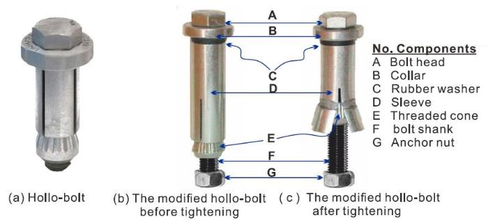
Figure 1.
Schematic diagram of anchored Hollo-Bolt
However, given that the structure of ABB CFT column connections is complex, their structural forms and relevant variable parameters are numerous. It is uneconomical and infeasible to study every influencing factor through tests. As an alternative, FEA can be used to study the nonlinear performance of ABB connections. The established FE model can be further utilized in the comprehensive finite element nonlinear parameter analysis on the different forms and structures of such connections.
In this study, a FE model of the ABB connections to CFT columns was established using the FEA software ABAQUS. The modified Hollo-Bolt shown in Figure 1(b) was selected as the anchored blind bolts. The elastoplasticity, large deformation, and contact problems were considered in the simulation. The results of six ABB flush endplate connections to CFT columns were used to be consistent with the FE model. Finally, a reasonable FE model for such connections was established. The load transfer modes and stress distribution of the ABB connections to CFT columns were analyzed using the verified FE model. The influencing factors on the performance of such connections were also analyzed. Furthermore, the effects of strength grade of bolts, thickness of endplates, vertical interval between bolts, diameter of bolts, and pretensionon bolts on the connections were analyzed. The analysis results provide a reference for the design of anchored blind-bolted connections to CFT columns.
2. Finite Element Modeling
In view of the material nonlinearity, geometric nonlinearity, and contact nonlinearity, the FEA software ABAQUS is adopted for the finite element analysis in this study, as the software has a strong nonlinearity function and allows for a convenient contact analysis.
2.1. Material Models
In consideration of the plastic hardening of the material and incremental theory of plasticity, ideal plastic material is added to guarantee certain hardening characteristics. The stress-strain relationship of the steel can be simplified as Figure 2, with the material constitutive curve presented by Bahaari and Sherbourne [12]. The Mises yield criterion is adopted to judge yield point of steel in the multiaxial stress state. When the equivalent stress of the steel exceeds the yield stress, the steel will undergo plastic deformation.
Figure 2.
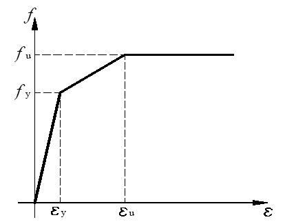
Figure 2.
Trilinear model
The plastic damage model is used for the concrete material model.The core concrete in the CFT is restricted by the steel tubes; thus, its properties are changed, that is, the plasticity of the concrete increases.The common uniaxial loading tests of concrete cannot reflect the change in plastic performance. Confinement of steel tubes to core concrete is considered by modified peak stress and descending line of the constitutive curve plateaus in the model. The uniaxial constitutive model advised by Han et al.[13] is adopted for the core concrete as follows:
Wherex=ɛ/ɛ0,y=σ/σ0,ɛ0=ɛc+800ɛ0.2
For rectangular steel tubes,
Where ξ is the confinement factor.
2.2. Finite Element Modeling
The FE model is established using ABAQUS. All parts are modeled using the solid C3D8R, a linear displacement interpolation brick with reduced integration. The model is divided into six parts, namely endplate, h-shaped beam, steel tubular wall, bolt, sleeve, and concrete. In order to simplify the model, the bolt and nut are placed in same component, and the influence of welding is ignored. The h-shaped beam and endplate are tied, and the other components are connected using the tangential penalty function and normal hard contact. The shapes and mesh division diagrams of the components are shown in Figure 3. Numerous elements are generated by the refinement of the concrete mesh; thus, half of the symmetric model is adopted to improve the calculation efficiency. The model assembly is shown in Figure 4. As the test loading is controlled by displacement, the finite element load is applied by establishing reference points coupled with the loading surface and by applying a certain displacement value.
Figure 3.
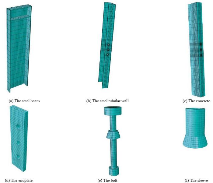
Figure 3.
Mesh division diagrams of the different components
Figure 4.
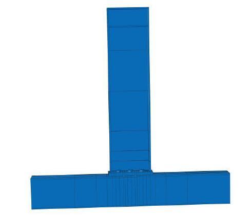
Figure 4.
Model assembly diagram
3. Test Overview
Six ABB flush endplate connections were designed to connect h-shapeds to square CFT columns. The details of the specimens are shown in Table 1. A schematic diagram of connection specimens is shown in Figure 5. The blind bolts adopted the modified grade 8.8 M16 Hollo-Bolt with an anchored nut. The anchorage depth of the nut was 90mm. The CFT column had a cross section of 250×250mm. The variable parameters were the column wall thickness, endplate thickness steel beam section, and anchorage method. Here, the column wall thickness could be changed by the plug welding of two 7 mm-C-shaped channels around the column wall in panel zone. The Hollo-Bolt used in specimen ST-5 was not anchored with a nut at the end of the threaded rod. Q235 steel was used for the weak beam flange and web in specimen ST-5, and the other steel material was Q345 steel. The compression strength and elastic modulus of concrete were 39.92MPa and 3.27×10⁴MPa, respectively. The nominal yield stress of the grade 8.8 M16 Hollo-Bolt was 640MPa, and the ultimate stress was 800MPa. The elastic modulus of the Hollo-Bolt was 206GPa.
Table 1. Details of test specimens(Unit: mm)
| Specimen | Column section | Column length | Beam section | Beam length | Endplate thickness | Local reinforcement | Anchorage method |
|---|---|---|---|---|---|---|---|
| ST-1 | 250×5 | 1736 | HN350×175×7×11 | 1400 | 12 | None | Nut |
| ST-2 | 250×5 | 1736 | HN350×175×7×11 | 1400 | 24 | None | Nut |
| ST-3 | 250×5 | 1736 | HN350×175×7×11 | 1400 | 12 | With | Nut |
| ST-4 | 250×5 | 1736 | HN350×175×7×11 | 1400 | 24 | With | Nut |
| ST-5 | 250×5 | 1736 | HN350×175×7×11 | 1400 | 24 | With | No |
| ST-6 | 250×5 | 1736 | HN300×150×6×9 | 1400 | 24 | With | Nut |
Figure 5.
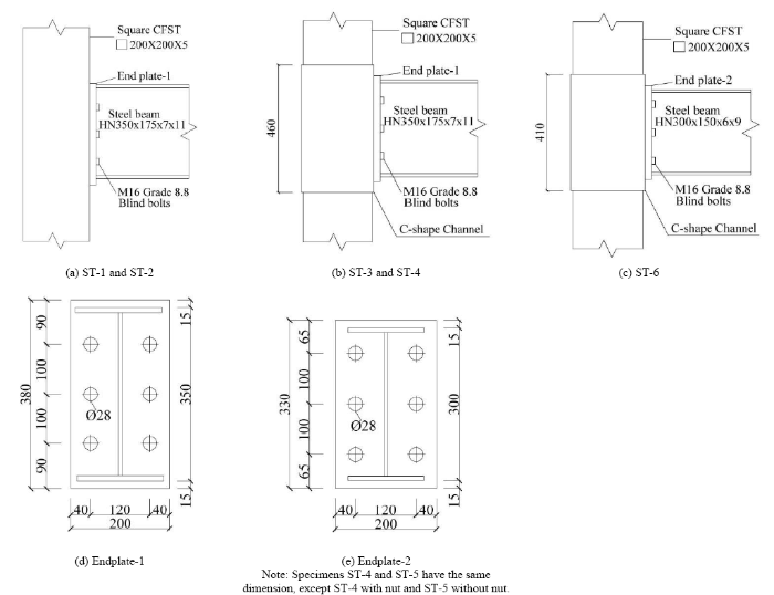
Figure 5.
Schematic diagram of joint specimens
The test setup is shown in Figure 6. The beam was connected to the MTS hydraulic actuator through the loading plate. Both ends of CFTs were hinged with the reaction wall. Using a hydraulic jack, A 980kN axial load was applied to the column. The ratio of axial load was 0.3 for the CFT columns. The loading was controlled by progressive displacement as suggested by SAC-97 1997 [14](Figure 7). The test terminated when the connections could not carry loads or the loading device limit was reached.
Figure 6.
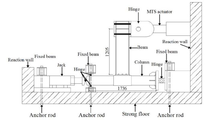
Figure 6.
Schematic diagram of testsetup
Figure 7.
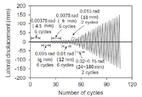
Figure 7.
Loading protocol
4. Finite Element Analysis and Test Result Comparison
The FE modelswere established and solved using the ABAQUS software. The moment-rotation curves attained by the numerical calculations are in comparison with the moment-rotation envelope curves obtained from the tests, as shown in Figure 8.The curves of specimens ST-1, ST-2, and ST-5 basically coincide in the early stage and demonstrate a few errors in the latter stage. The curves of the three other specimens basically coincide. The deviation between the curves is mainly caused by the following factors: (a) specimens ST-1, ST-2, and ST-5 suffer from severe concrete damage in the post-peak stage of test; (b) uncontrollable objective factors and human errors occurred during the test and cannot be considered in the FE model.
Figure 8.
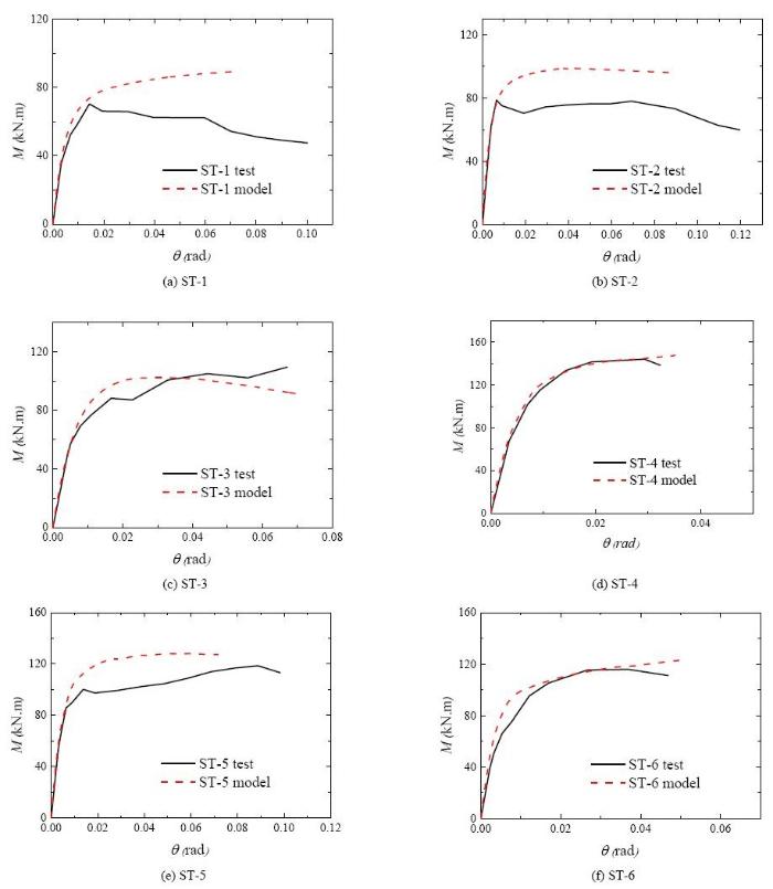
Figure 8.
Comparison of test and finite element moment-rotation curves
As shown in Figure 9, the comparison between failure modes of FEA and test shows that endplates in the finite element and in the test have undergone similar deformation, whether involving the thick endplate or the thin endplate. The weak beam connection in the test and FE model buckled at the root of the beam. The test and FE model basically have the similar failure modes. Therefore, the FE model is consistent with the tests and can be used for parameter analysis.
Figure 9.
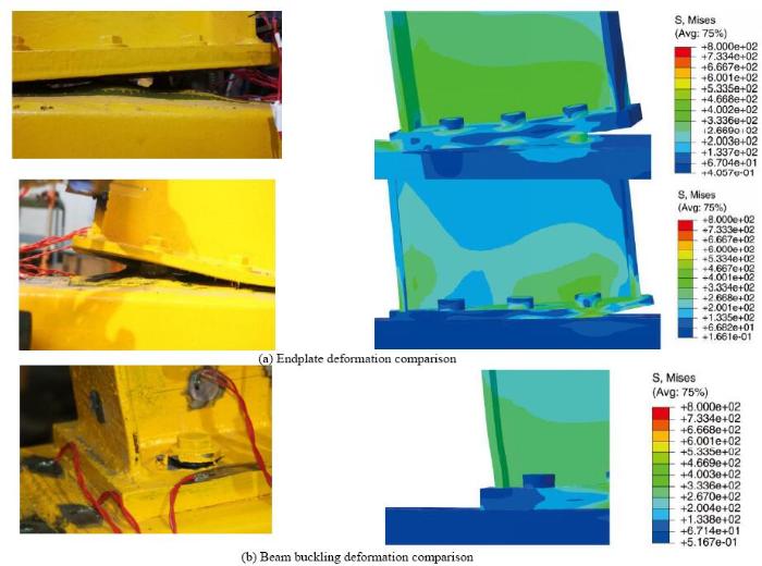
Figure 9.
Comparison of the test and finite element failure modes
5. Analysis on Loading Transmission Mode
In the traditional CFT column connections, the load in the tensile area is mainly transmitted to the endplate through tensile flange of the h-shaped beam; thus, the endplate is bent. Subsequently, the load is transmitted to tubular wall of steel column through the bolts, leading to its apparent outward deformation of the tube.
However, the ABB connections to CFT columns, which are equipped with anchored bolts outrigger into the core concrete, effectively limit the outside deformation of the tubular walls. Thus, the load transmission mode and stress distribution of the anchored blind-bolted connections to CFT columns are different than those of the traditional CFT column connections. On the basis of the verified FEA results of specimen ST-4, the internal stress distribution of the CFT column corresponding to the maximum momentis shown in Figure 10. The tensile force can be effectively transmitted to the entire threaded rod up to the anchored nut, indicating that the anchoring device can completely perform its function. The threaded rod transmits the tensile force to the concrete through the anchorage. The force transmission area is generally the cone with the anchor end as the vertex. The tensile force is then transmitted to the upper steel tubular wall. According to the FEA results, the diffusion angle of the cone is approximately 60°. Therefore, the area of the stress transmitted to the steel tubular wall is much higher than that of the connections without anchored bolts, in that the steel tubular wall is more uniformly stressed to achieve a smaller deformation. In addition, the stress is obviously concentrated at the anchored nut and around the sleeves. This result is consistent with the concrete deformation in the test. In conclusion, the transmission path of the load in the tensile area is given as follows: Steel beam--endplate--bolt--anchoring concrete--column wall. Clear description of the load transmission mode and stress distribution of the anchored blind-bolted connections to CFT column can facilitate the derivation of the calculation models and formulation for the rigidity and moment bearing capacity of such connections.
Figure 10.
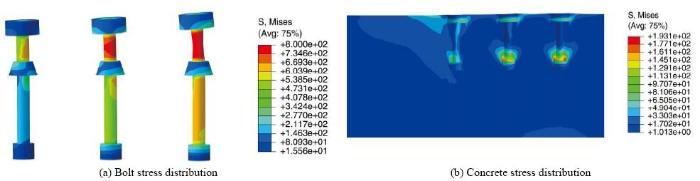
Figure 10.
Stress distributions of the CFST columns
6. Parameter Analysis
The influences of strength grade of bolts, thickness of endplates, vertical interval between bolts, diameter of bolts, and pretension on bolts on the characteristics of the ABB connections to CFT columns were analyzed using the verified FE model. The basic calculating model included local reinforced CFT column, steel beam (HN350×175×7×11mm), and modified Hollo-Bolt.
6.1. Influence of Strength Grade of Bolts
The influence of strength grade of bolts on the moment-rotation curve of the connection is shown in Figure 11, which indicates that the strength grade of bolts does not influence the initial rotation stiffness of the connection. However, as the rotation of the connection increases, the connection with higher strength of bolts exhibits higher moment capacity. These results show that an increase in the bolt strength grade poses a certain influence on enhancing the rotation ability of the connection.
Figure 11.
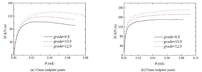
Figure 11.
Influence of strength grade of bolts on connection performance
6.2. Influence of Thickness of Endplates
The influence of endplate thickness on the moment-rotation curve of the connection is shown in Figure 12, which indicates that the connection moment bearing capacity is increased with an increase in the thickness ofendplates, but the yield rotation of the connection is decreased with an increase in the thickness ofendplates,resulting ina low connection ductility. Furthermore, the initial stiffness of the connection increases with an increase in the endplate thickness. However, when the endplate reaches a certain thickness value, the influence on the initial stiffness of the connection is minimal with the increase in the endplate thickness.
Figure 12.
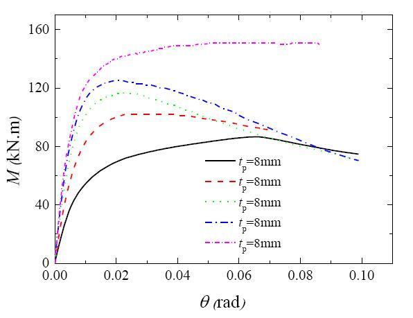
Figure 12.
Influence of thickness of endplates on connection performance
6.3. Influence of Vertical Interval Between Bolts
The influence on the moment-rotation curves of the connection by vertical interval between bolts is shown in Figure 13, which indicates that the initial rigidity increases with an increase in the vertical interval between bolts, but the vertical interval has limited influence on the moment bearing capacity and yield moment of the connection. However, the curves show the corresponding connection rotation obviously increases with a decrease in the bolt interval. This result shows that a decrease in bolt interval can enable the bolt to reach the moment capacity at a larger rotation and increase the connection ductility. However, the connection stiffness can be low in the initial period. Therefore, the vertical connection spacing should be appropriate.
Figure 13.
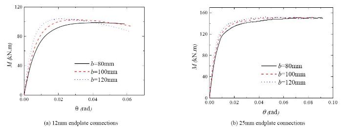
Figure 13.
Influence of vertical interval between bolts on connection performance
6.4. Influence of Diameter of Bolts
The influence of diameter of bolts on the moment-rotation curves of the connection is shown in Figure 14, which indicates that an increase in the bolt diameter can increase the initial rigidity and moment bearing capacity of the connection. The equivalent plastic strains of bolts in the FEA models are drawn. When the load displacement angle of the thick endplate specimens reaches 0.04 (load displacement angle upon the ST-4 connection at the failure in the test), the equivalent plastic strains of the M16-M20 bolts are 0.35, 0.31, and 0.22, respectively. These results show that the deformability increases with an increase in the bolt diameter. Hence, an increase in the bolt diameter is an efficient strategy to improve the bolt deformability.
Figure 14.
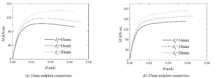
Figure 14.
Influence of diameter of bolts on connection performance
6.5. Influence of Pretensionon Bolts
The influence of pretensionon bolts on the moment-rotation curve of the connection is shown in Figure 15. The pretension forces imposed on the grade 8.8 bolts and the grade 10.9 bolts are 70 and 100 kN respectively, in accordance with Chinese code GB50017-2003 [15]. The moment-rotation curves of both the grades 8.8 and 10.9 bolts basically coincide, indicating that different from common high-strength bolts, blind bolts aim to connect the hollow rectangular steel tubes and H-shaped beams by preloaded bolts before concrete is cast,and the anchoring role of concrete has a prominent influence on the connection performance when the load is appliedon the connection. In this situation, the bolt pretension force has nearly no effect on the connection performance.
Figure 15.
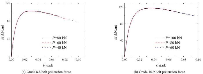
Figure 15.
Influence of pretension force on connection performance
7. Stiffness Classification
According to EC3 Parts 1-8 [16], a connection can be classified as nominally pinned, semi-rigid, or rigid, depending on its rotational capacity. The detailed regulations are as follows:
Rigid connection:Ki >kbEbIb/Lb;
Nominally pinned connection: Ki <0.5kbEbIb/Lb;
Semi-rigid connection: 0.5kbEbIb/Lb<Ki<kbEbIb/Lb.
Where E is the elastic modulus of steel, Ib is the moment of inertia of the h-section steel beam, Lb is the beam span, and kb=8 is for the no-sway frame or kb=8 is for the sway frame. Therefore, all the six connections for test and 15 connections for FEA are semi-rigid ones. Therefore, the ABBflush endplate connections to CFT columns are typical semi-rigid connections.
8. Conclusions
The ABB connections to CFT columns were modeled and analyzed using the FEA software ABAQUS. The finite element and test results were compared and analyzed. The relevant parameters of the finite elements were also analyzed. The conclusions are drawn as follows:
(1) The FEA models were validated against the moment-rotation curves and the failure modes (the experimental observations) of the tested connections. The comparisonsshow that the FEmodel can excellently simulate the characteristics of the ABB connections to CFT columns.
(2) The tensile force can be effectively transmitted to the entire threaded rodup to the anchor nut, indicating that the anchoring device can completely perform its function. The threaded rod transmits the tensile force to the concrete through the anchorage. The force transmission area is generally the cone with the anchor end as the vertex. The tensile force is then transmitted to the upper steel tubular wall. According to the FEA results, the diffusion angle of the cone is approximately 60°.
(3) The initial rigidity and moment bearing capacity of the connection are influenced by endplate thickness and bolt diameter. The strength grade of bolts exerts an important influence on the moment bearing capacity, and the vertical interval between bolts mainly influences the initial stiffness. The bolt pretension force has minimal influence on the connection performance. According to the results of FEA, in engineering, the blind bolts can be strengthened by increasing the diameter of bolts, appropriately improving the strength grade of bolts and adopting an appropriate vertical interval between bolts in practical engineering.
(4) According to EC3 Parts 1-8, the ABB flush endplate connections to CFT columns are typical semi-rigid connections.
Acknowledgments
This work was financially supported through grants fromthe National Nature Science Foundation of China(No. 51638009,51778241), State Key Laboratory of Subtropical Building Science, and South China University of Technology (No. 2017ZB28, 2017KD22). The authors thank the two anonymous reviewers for their helpful suggestions.
Reference
“Developments and Advanced Applications of Concrete-Filled Steel Tubular (CFST) Structures: Members,”
DOI:10.1016/j.jcsr.2014.04.016
URL
[Cited within: 1]

61We summarize various types of CFST members.61We advise research framework and a recent research review on CFST members.61We present various projects using CFST members in China.
“Behaviour of Blind Bolted Connections to Concrete Filled Hollow Sections,”
“Experimental Monotonic and Cyclic Behaviour of Blind-Bolted Angle Connections,”
DOI:10.1016/j.engstruct.2009.05.021
URL
[Cited within: 1]

This paper deals with the experimental behaviour of blind-bolted angle connections between open beams and tubular columns. A number of connection configurations with different geometric arrangements and bolt properties are examined. The experimental set-up, connection details and material properties are first described. A detailed account of the results and observations from seventeen monotonic and cyclic connection tests is then presented, and the main behavioural aspects are discussed. The specimens include connections with top and seat angles as well as others in which web angles are also incorporated. The experimental results offer direct information on the influence of important geometric and material properties, such as angle dimensions, column face thickness, gauge length and bolt class, on the key response characteristics including stiffness, strength, energy dissipation and failure mechanism. Based on the findings, simplified approaches through which the initial stiffness and yield parameters can be estimated, are assessed. The test results also provide essential data for the future validation of detailed numerical and analytical studies which can be employed for further assessment of the response, with a view to the development of design-oriented procedures.
“Seismic Response of Extended End Plate Joints to Concrete-Filled Steel Tubular Columns,”
DOI:10.1016/j.engstruct.2013.01.001
URL
[Cited within: 1]
This paper investigates the seismic behaviour of extended end plate connections to circular or square concrete-filled steel tubular (CFST) columns using blind bolts. Both the end plate type and the column section type are considered. Results of an experimental study involving four bolted moment-resisting connections subjected to cyclic loading are presented. The failure modes, hysteretic performance, strength and stiffness degradation, rigidity classification, and energy dissipation of the blind bolted extended end plate connections to CFST columns were estimated in detail to investigate the seismic behaviour. The anchorage action of reinforcing rebar welded to the bolt with concrete-filled steel tubes was also explored. The experimental results indicated the blind bolted extended end plate connections with circular or square CFST columns exhibited large hysteretic loops, good ductility, and excellent energy dissipation capacity. Failure modes for test specimens under cyclic loading were similar to those under monotonic loading, and their rotation capacities satisfied the ductility design requirements for earthquake-resistance in most seismic regions. These experimental studies enable improvement in the practical design of blind bolted moment connections.
“Behaviour of Flush End Plate Joints to Concrete-Filled Steel Tubular Columns,”
DOI:10.1016/j.jcsr.2008.10.010
URL
This paper presents the results of an experimental program for bolted moment connection joints of circular or square concrete filled steel tubular (CFST) columns, and H-shaped steel beams using high-strength blind bolts. In order to investigate the static performance and failure modes of the blind bolted connection, an experimental program was conducted involving four sub-assemblages of cruciform beam-to-column joints subjected to monotonic loading. Moment鈥搑otation relationships of the tested connections were obtained and their performance was evaluated in terms of their stiffness, moment capacities and ductility. The test parameters varied were the column section type and the thickness of the end plate. The results showed that the proposed blind bolted connection, which behaves in a semi-rigid and partial strength manner according to the EC3 specification, displays reasonable strength and stiffness. The rotation capacity of this type of connection to square or circular CFST columns exceeds 70 mrad and this satisfies the ductility requirements for earthquake-resistance in most aseismic regions. The blind bolted connection is shown to be a reliable and effective solution for moment-resisting composite frame structures.
“Experimental Investigation of Extended End Plate Joints to Concrete-Filled Steel Tubular Columns,”
DOI:10.1016/j.jcsr.2012.07.016
URL
[Cited within: 1]
An experimental programme to obtain the behaviour of blind bolted extended end plate joints to circular or square concrete-filled steel tubular (CFST) columns under monotonic loading has been conducted. In order to enhance the strength and stiffness of the connections, the anchorage extensions are provided to the blind bolts to link the connection back into the concrete with the tubular. This paper investigated the effect of the end plate thickness and the column section type on the static behaviour and failure modes of the tested connections. The structural performance of the blind bolted extended end plate connections was evaluated in terms of the moment otation relationship, connection rigidity, the deformation pattern and the strain response. The test results showed that the blind bolted extended end plate connection to CFST columns exhibits high strength and stiffness, while its connection rotation capacity satisfies the ductility requirement for earthquake resistance in aseismic region. The experimental studies also demonstrated that the strength and stiffness of the connections can be improved by providing anchorage extensions to the blind bolts, and utilising moderately thick end plates leads to joints approaching full strength for the extended end plate connections.
“The Performance of a New Blind-Bolt for Moment-Resisting Connections, ”
“Experimental Behaviour of a Novel Anchored Blind-Bolt in Tension,”
DOI:10.1016/j.engstruct.2012.12.023
URL
[Cited within: 1]
Current state-of-the-art models for steel and composite joints are based on the so-called component method. These models require knowledge of the behaviour of the relevant joint components, and also require an appropriate assembly procedure. Within the framework of the component method, this paper presents the results of an experimental programme for a novel blind-bolt component, whose application relates to the construction of moment-resisting joints between open profile beams and concrete-filled hollow section columns. The aim of the programme was to quantify the component level of pre-load, and to measure its full, non-linear force isplacement response. The latter was determined by monotonic pull-out tests. A total of 51 pull-out and 20 pre-load tests are reported. The test variables were the grade (or property class) and size of the internal bolt, the strength of the concrete infill, and the embedded depth. The load transfer mechanism of the component was investigated on the basis of the individual elements which contribute to its overall deformability; namely, the elongation of its internal bolt, and the slip of its expanding sleeves and mechanical anchorage elements. For the studied range, the test results demonstrate that the anchored blind-bolt component can ultimately provide resistance to pull-out, achieving the full tensile capacity of its internal bolt. This failure mode is comparable with that exhibited by standard bolts, illustrating the suitability of the component in resisting the predominant tensile loads expected in moment-resisting construction. Increasing the compressive strength of the concrete infill had the most enhancing effect on the tensile stiffness of the component.
“Rotational Stiffness of a Blind-Bolted Connection to Concrete-Filled Tubes using Modified Hollo-Bolt,”
DOI:10.1016/j.jcsr.2012.09.024
URL
[Cited within: 1]
Moment resisting connections to hollow sections tend to utilise welding and reinforcements to achieve the stiffness required to resist moment. Blind-bolted connections to hollow sections offer a simpler, more economical and construction-friendly means of connecting to hollow sections. Such connections have been used in nominally pinned connections and in non-primary structural connections. Exploratory research work has been done by a number of researchers to improve the stiffness of such bolted connections through the use of concrete filling. Concrete filling tends to improve the stiffness of the connection. However, the improvement is not sufficient to attain significant moment resistance allowing such connections to be classified as rigid connections. This is because they address only half of the problem. That is the flexibility of the tube face. This paper reports on a blind-bolted connection to concrete-filled square hollow sections using a modified blind-bolt that addresses the issue of the flexibility of the blind-bolt connector as well as that of the tube face. The paper reports on this novel connection type and on an experimental programme aimed at measuring the resulting connection stiffness. The programme tested eight full size connections, principally varying the connection endplate type, column thickness and concrete strength. The data was cross validated with a finite element model. The paper assesses the performance of this connection using connection stiffness classification methods. It concludes that the connection is able to develop the required stiffness for it to be used as a rigid connection in braced frames. (C) 2012 Elsevier Ltd. All rights reserved.
“Hysteretic Performance of a New Blind Bolted Connection to Concrete Filled Columns under Cyclic Loading: An Experimental Investigation,”
“Performance of T-Stub to CFT Joints using Blind Bolts with Headed Anchors,”
“Behavior of Eight-Bolt Large Capacity End PlateConnections,”
DOI:10.1016/S0045-7949(99)00218-7
URL
[Cited within: 1]
Only a limited number of experimental and analytical reports exist concerning large capacity, eight-bolt, extended endplate connections. This paper describes the structural properties, both stiffness and strength, of an extended endplate connected to a column flange, with no stiffeners in either tension or compression region, using eight high strength fully and partially prestressed bolts. The case studies considered in this paper offer greater insight into the significance of endplate and column flange interaction and bolt positioning; besides the displacement and stress distributions, the prying phenomenon is also addressed. The methodology is based on a finite element modeling developed previously for the standard four-bolt array. ANSYS, version 4.4, a large-scale general purpose code is selected for equivalent three-dimensional (3D) analysis. The end-plate, beam and column flanges and web are represented as plate elements. Each bolt shank is modeled using six spar elements. 3D interface elements are used to model the boundary between column flange and back of the end-plate that may make or break contact.
“Tests and Calculations for Hollow Structural Steel (HSS) Stub Columns Filled with Self-Consolidating Concrete (SCC),”
ENV1993-1-8, Eurocode 3: Design of steel structures-Part 1-8: Design of joints.
