


1.Introduction
Many engineering components and structures in service are working under circumstances of high temperatures, high speed, and corrosion. It is advisable to conduct nondestructive inspections for monitor corrosion, cracks, and other defects[1]. However, the traditional non-destructive test (NDT) techniques, such as linear ultrasonic testing (UT), Eddy current testing (ET), and magnetic flux leakage testing (MT), are mainly used to detect already developed defects [2-4]. The metal magnetic memory (MMM) technique, proposed by Russian experts in the late 1990s, has become an emerging field recently due to its capability of early diagnosis and pre-warning of dangerous ferromagnetic work pieces and parts involving the characteristic of precise stress concentration [5-7].
MMM is a nondestructive testing method based on the analysis of self-magnetic leakage field (SMLF) distribution on components’ surfaces for the determination of stress concentration zones, imperfections, and heterogeneity of metal structures and welded joints.Because the physical mechanism of MMM method is still unclear so far, many researchers have devoted their efforts to investigate variation regularities of MMM signals in the laboratory. Previous research on the MMM method concentrated on the variation of MMM signal under tensile stresses, cyclic tensile-compressive stress, and the magnetomechanical effect, and the physical mechanism of the metal magnetic memory phenomenon has also been discussed in rotary bending fatigue experiments [8-11]. Although several experimental studies have been carried out and many important achievements have been made, most of the research focuses on analyzing normal components of magnetic leakage fields, and little work has been done on MMM engineering signal processing.
The real signals measured in engineering practice usually contain interference noise. Since SMLF is a kind of weak magnetic field and is sensitive to noise, the background magnetic field and measurement noise have a great impact on flaw inspection. The higher the sampling frequency, the greater the influence of the same noise, so it is hardly pressed to distinguish the stress concentration zones directly. In this paper, a new detection strategy was presented to reduce the influence of background magnetic field, and multi-scale morphological filtering, a kind of nonlinear filter, was adopted to suppress various kinds of measurement noise.
2. Research on the Background Magnetic Interference Elimination
There are many kinds of magnetic testing instrumentsthat can be used in the MMM test, and the instruments can be divided into single-channel and multi-channel according to the number of detection channels. Theycan also be divided into one-dimensional, two-dimensional, and three-dimensional according to the dimensions of the testing magnetic field. However, most of the magnetic testing equipment have a common characteristic: the magnetic sensors are arranged in the same horizontal plane. When detecting the surface magnetic field of the ferromagnetic specimens, the real magnetic field signal H measured in engineering practice can be expressed as
Where Hp is the magnetic field generated by the stress concentration zones (SCZs), Hb is the background magnetic field consisting of the magnetic field caused by other equipment, the geomagnetic field, and the induced magnetic of the test specimen itself. Hz is the measurement noise produced by the test system itself. The magnetic memory signal is not only affected by the measurement noise Hz but also influenced by the background magnetic field Hb. The signal processing technique can only reduce the interference of Hzbecause the background magnetic field Hb cannot be known or controlled in advance. Therefore, it is hard to distinguish the SCZs directly, while the maximum magnetic field gradient value has more advantages. Because the magnetic field gradient value is obtained from the first derivation of the real signals, when Hb changes slowly and smoothly, the influence of the background magnetic field on the magnetic field gradient can be ignored, but if Hb changes in a complicated and volatile manner, the background magnetic will have a great impact on the SMLF distribution and gradient.
The SMLF signal is affected by the SCZ width, location, and lift-off value of sensors, but the lift-off has a much greater impact on the SMLF signal than other factors. As shown in Figure 1, the amplitude of the SMLF signal drops dramatically when the lift-off value increases within a small range; therefore, the probe should be as close to the test specimen surface as possible in engineering tests [12].
Figure 1.
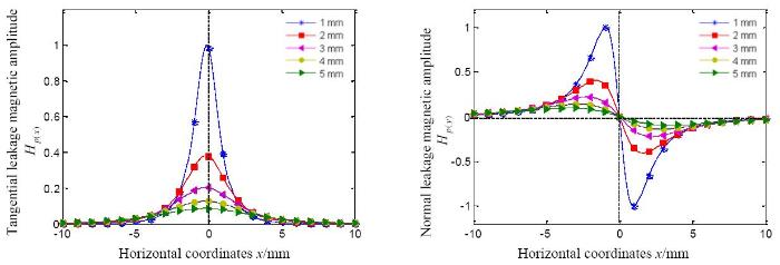
Figure 1.
The effect of lift-off value on the distribution of SMLF signals
Because the lift-off has a great impact on the SMLF, a double-sensor probe is designed as shown in Figure 2.
Figure 2.
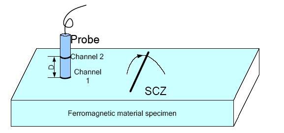
Figure 2.
Schematic diagram of magnetic memory test
Since the test specimen volume is much bigger than the SCZ volume and the distance from the environment magnetic field source to the probe is much longer than the distance of D between the two magnetic sensors, the background magnetic field signals measured by the two sensors is approximately the same while the SMLF signals has a large difference. The channel 1 test signal is the detection signal, and the channel 2 test signal is the compensation signal. The channel compensated method can eliminate the influence of the background magnetic field.
As Figure 3 shows, a specimen with an appreciable SCZ was inspected by the MMM method. The magnetic flux leakage was measured by magnetic sensor HMC5883L produced by Honeywell, and the lift-offs of the two sensors were 1mm and 4mm. The magnetic field signals were recorded along the specimen length direction line and scanned by a step of 0.2mm.
Figure 3.
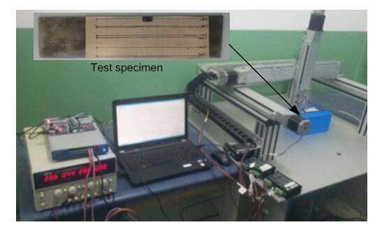
Figure 3.
Photo of experiment
Figure 4 shows the detection result of a ferromagnetic specimen. The curves Ch1 and Ch2 were measured by channel 1 and channel 2 respectively, and the curve Ch1-Ch2 was the differential signal of Ch1 and Ch2. It is obvious that the differential signal removed the stable interference of the background magnetic field and protected the detail of the SMLF signal well, and it also has the advantage of anti-electromagnetic interference.
Figure 4.
Figure 4.
Detection result of metal magnetic memory
3. Research on the Measurement Noise Interference Elimination
The channel compensated method can reduce the interference of the environment magnetic field and equipment working electromagnetic, but it cannot avoid the influence of measurement noise. Because the SMLF belongs to a non-stationary signal, the application of a self-adaptive digital filtering is limited. Therefore, we try to seek a new method to reduce the measurement noise and introduce morphological filtering into SMLF signal processing. Morphological filtering is a kind of nonlinear filtering method that has good filter performance and good flexibility, and it is widely used in vision detection, noise suppressing, edge extraction, and pattern recognition. In this paper, we discuss mainly the basic theory of morphological filtering, design the structuring elements according to the characteristics of the SMLF signal, and propose a multi-scale morphology filtering for denoising.
3.1. Introduction of Morphological Filtering
There are four kinds of basic mathematical morphological transformation[13]: dilation, erosion, opening, and closing. Let f(n) be a discrete real function on the one-dimensional space Z, and structure element g(m) the subset of Z. Then,dilation($\Theta $) and erosion($\oplus $) f(n) with respect to g(m) are defined as follows:
Morphological opening($\circ$) and closing($\centerdot$) of (n) with respect to g(m) are
Morphological opening-closing and closing-opening filters are defined as follows:
Where OC is denoted as an opening operation followed by a closing operation and CO is denoted as a closing operation followed by an opening operation. Through the cascade connection of opening and closing, both the positive and negative noise can be eliminated using the same structure element. Moreover, to weaken the statistical deviation problem existing in open-closing and close-opening filters, the two filters are combined together to form a new filter:
3.2. Selection of Structure Element
The selection of the structure element includes the selection of the shape, the width, and the height. According to reference [14], the selection of the structuring element has a great influence on the effect of the filtering. In order to get a good filtering effect, the structuring element should be similar to the useful signal. We propose the structuring elements in the light of tangential and normal magnetic signals of SMLF as follows:
The shapes of the proposed structuring elements are shown inFigure 5, and we can adjust the value of L and k to control the width and height of the structuring elements.
Figure 5.
Figure 5.
Shape of structure element
3.3. Multi-Scale Morphological Filter
The selection of structuring element width on the filtering effect is the most important. If the width of the structuring element is too small, the noise cannot be removed completely. On the contrary, if the width is too large, the wanted signal will be distorted. In order to remove the noise completely and preserve the features of the SMLF signal, a multi-scale morphology filter was proposed[15]. The multi-scale morphological opening and closing are defined as
Where sg is the width of structuring element s. The multi-scale morphology filtering algorithm is illustrated in Figure 6.
Figure 6.
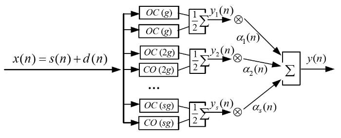
Figure 6.
The diagram of the adaptive multi-scale morphological algorithm
Where x(n) is the input signal, s(n) is the noise-free signal, d(n) is the noise signal, ys(n) is the output signal after the combined morphology filter in which the width of the structuring element is s, αi(n) is the weight of yi(n), andy(n) is the final output signal that can be expressed as
The difference between the filter output y(n) and s(n) is
The mean square error is
Meanwhile, there exists
When the mean square error reaches its minimum, $\nabla =0$. According to the gradient descent method,
Where μ is the learn rate andi is the order of the filter arm. Since the noise-free signal cannot be known in practice, we can use the input signal x(n+1) to replace s(n).
3.4. Comparison of the Effects of Morphological Filtering with those of Conventional Filtering
In MMM testing signal processing, there are many other noise reducing methods, such as wavelet filtering and neighbor average filtering. Now, we make a comparison of the effects of morphological filtering, wavelet filtering, and neighbor average filtering.
In this simulation experiment, the expression of noise-free signal is $y(t)=2\sin (2\pi ft)$(in which f=1, t=0 ~ 10, and the interval is 0.01), and the mixed noise signal consists of Gaussian noise, positive impulse noise, and negative impulse noise. The structuring element shape of morphological filtering used in the experiment is a straight line, and the width is 5. The wavelet basis function of wavelet filtering is db8, and the number of wavelet decompositions is 6. The window width of the neighbour average filter is 5.
Figure 7 shows the effects of removing random and impulse noise with the three kinds of filter.
Figure 7.
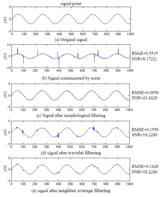
Figure 7.
Comparison among the denoisingresults of different methods
From the shape, the root mean square error (RMSE), and signal to noise ratio (SNR), we can see that the effect of morphological filtering is better than the other two. The effects of wavelet filtering largely depend on the chosen wavelet basis function. Nevertheless, the frequency and amplitude of noise are changing and unpredictable, so it is not easy to choose a suitable wavelet basis function that is not self-adaptive. Neighbour average filtering can reduce the interference of Gaussian noise, but it cannot remove the influence of impulse noise. Morphological filtering transforms the test signal with the structuring element of a certain shape, measuring and picking up the corresponding shape in the test signal; thus, morphological filtering should not care about the characteristic of noise.
In order to ensure the suitable range value of the structuring element width, we suppress the noise filtering with different widths of the structuring element. The effects of different widths of the structuring element are shown inFigure 8.
Figure 8.
Figure 8.
The morphological filtering wave by different scale length
Therefore, we should select a proper width range value based on the character of the SMLF signal. As for the SMLF signal, supposing the greatest width of the SCZs signal is T and the sample interval is Ts, the greatest width of the structuring element needs to be slightly less than T/Ts to remove the mixed noise. In this experiment, for the tangential signal of SMLF, the greatest width of the structuring element chooses 9, and for the normal signal of SMLF, the greatest width of the structuring element chooses 11. The final effects of multi-scale morphology filtering are shown in Figure 9. Since the weight coefficient was set according to the error of each filter, multi-scale morphology filtering can remove the noise completely and preserve the features of the wanted signal.
Figure 9.
Figure 9.
The signal after multi-scale morphological filtering
4.Conclusions
MMM is an effective method for early diagnosis of structural failure or fatigue damage, but the real MMM signals method always contains much inference noise. Therefore, it is necessary and important to study the method of SMLF signal extraction and noise reduction in engineering.
As a substitute for the existing SMLF measurement methods, the channel compensation program can eliminate interference by the static background magnetic field and dynamic magnetic field. It reduced the MMM method’s requirements of the test environment.
The morphological filtering is totally self-adaptive and does not need manual intervention. The speed of calculation of the method is very high because the operation only involves addition and subtraction. With the structure elements built according to the SMLF signal characteristics, multi-scale morphological filtering achieved good performance in reducing pulse noise and random noise, while preserving the feature of the SMLF signal.
We should select a proper distance between two channels. If the distance is too long, the residual magnetic of specimen attenuates and the background magnetic field cannot be separated completely. On the contrary, if the distance is too short, the wanted signal in the differential signal will be lost. The proper distance can be determined by testing; however, further work will be required to select the distance of two channels according to the detection position and volume of the specimen.
Acknowledgments
We would like to thank the reviewers for their valuable comments. This work was partially funded by the National Natural Science Foundation of China and the Military Research Foundation of China.
Reference
“Thermo-Magneto-Elastoplastic Coupling Model of Metal Magnetic Memory Testing Method for Ferromagnetic Materials,”
“Research on Methods of Defect Classification based on Metal Magnetic Memory,”
“A Study of Metal Properties using the Method of Magnetic Memory”
,The article is devoted to the results of a laboratory and industrial study that shows that the suggested criterion can be used as an integral diagnostic parameter of the state of new and old (operating) parts made of a ferromagnetic material. The main criterion in diagnosing the equipment by the method of magnetic memory of the metal is the determination of the zones of stress concentration (SC) on the surface of the controlled part, which are characterized by changes in the sign of the field of residual magnetization H sc or a line on the surface characterized by a zero normal component of the field H sc . The field H sc is measured by a special IMNM-1F magnetometer produced by the nergodiagnostika Research and Production Association.
“The Metal Magnetic Memory Method Application for Online Monitoring of Damage Development in Steel Pipes and Welded Joints Specimens,”
DOI:10.1007/s40194-012-0011-5
URL
[Cited within: 1]

The magnetic memory of metal (MMM) is an after-effect, which occurs in the form of metal residual magnetization in components and welded joints formed in the course of their fabrication and cooling in the weak magnetic field of the earth and in the form of irreversible change of components’ magnetization in zones of stress concentration and damages under working loads (ISO 24497–1:2007(E)). The results of experimental investigation by the metal magnetic memory of steel specimens in the process of their static and cyclic loading are presented. Investigation using the MMM method was carried out online in the process of cyclic loading in the synchronous manner with load frequency. Specific features of self-magnetic field’s (SMLF) intensity variation at maximum load during tensile cyclic load were revealed. The obtained results of specimens investigation experimentally confirmed the earlier drawn conclusion about the possibility of the MMM method and corresponding inspection instruments application for quick testing of mechanical properties and cyclic strength parameters at the physical level. Comparison of σ – ε deformation curves and σ –∆ H x , ∆ H x –ε magnetograms, obtained in the static loading mode, of σ – ε cyclic loading profiles and corresponding magnetograms confirms once more the earlier established correlation of magnetomechanical parameters conditioned by the “magnetodislocation hysteresis”. Fatigue curves, plotted by variation of the self-magnetic field of the specimens in the process of cyclic loading, experimentally confirm the possibility of equipment life assessment by parameters of the metal’s magnetic memory. Magnetograms, recorded online in the process of cyclic loading of specimens, allow claiming the possibility of the MMM method and the Tester of Stress Concentration type instruments application for technical state monitoring during operation of equipment under load conditions.
“Quantitative Characterization of Stress Concentration of Low-Carbon Steel by Metal Magnetic Memory Testing,”
“Study on Characteristics of Magnetic Memory Testing Signal based on the Stress Concentration Field”
,
DOI:10.1049/iet-smt.2015.0119
URL
Metal magnetic memory testing technology has been effectively used in stress concentration areas and micro-cracks detection of ferromagnetic metal components. However, due to the lack of profound theoretical basis and effective experimental research, the magnetic memory signal characteristics and magnetism quantitative relationship has not yet been determined. In this study, the full electronic potential magneto-mechanical model is established which is using the norm conserving pseudo-potential algorithm based on the first-principle. The quantitative relationship is then calculated between the stress concentration and the magnetic memory signal. The calculation results show that the changes of the wave function, which result from the stress concentration in the solid band, are the fundamental cause of the magnetic memory phenomenon, and atomic magnetic moment, lattice constant and the magnetic flux leakage signal strength linearly changes as a function of stress trend. As the stress concentration reached the critical stress point, the lattice structure was damaged, and the magnetic memory signal had undergone mutation. In this study, the experimental results are consistent with the theoretical calculation results.
“Mapping of Deformation-Induced Magnetic Fields in Carbon Steels using a GMR Sensor based Metal Magnetic Memory Technique”
,
DOI:10.1007/s10921-018-0470-8
URL
[Cited within: 1]
Giant magneto-resistive (GMR) sensor based metal magnetic memory (MMM) technique is proposed for mapping of deformation-induced self-magnetic leakage fields (SMLFs) in carbon steel. The specimens...
“On Problems of Applicability of the Metal Magnetic-Memory Method in Testing the Stressed-Deformed State of Metallic Constructions”
,
DOI:10.1134/S1061830909080026
URL
[Cited within: 1]
Experimental data on the effect of stresses on magnetic properties of specimens made of ferromagnetic steel produced by a hot-rolling section mill at the JSC Magnitogorsk Metallurgical Works are reported. The coincidence of points of the sign reversal of the normal component of a stray magnetic field at the specimen surface and the failure sites of the specimens, which were predicted by the “metal magnetic-memory method,” was shown to have a random character.
“A Ferromagnetic Disk in aConstant Axially Symmetric Inhomogeneous Magnetic Field”
,
DOI:10.1134/S1061830915030080
URL
The distorting effect of a ferromagnetic disk of finite dimensions on the constant field of a magnetic dipole is considered. It is shown that, depending on the mutual arrangement of the dipole and disk, the dipole field may be both intensified and attenuated. It was proposed for the first time to use an additional ferromagnetic disk in order to attenuate the shielding effect of a ferromagnetic disk on a dipole field. The theoretical considerations were confirmed by the experimental results. The presented information can be useful when organizing testing of the magnetic fields of objects that are placed behind a ferromagnetic obstacle.
“Fatigue Damage Evaluation by Metal Magnetic Memory Testing,”
Tension-compression fatigue test was performed on 0.45% C steel specimens.Normal and tangential components of magnetic memory testing signals,Hp(y) and Hp(x) signals,with their characteristics,K of Hp(y) and Hp(x)M of Hp(x),throughout the fatigue process were presented and analyzed.Abnormal peaks of Hp(y) and peak of Hp(x) reversed after loading; Hp(y) curves rotated clockwise and Hp(x) curves elevated significantly with the increase of fatigue cycle number at the first a few fatigue cycles,both Hp(y) and Hp(x) curves were stable after that,the amplitude of abnormal peaks of Hp(y) and peak value of Hp(x) increased more quickly after fatigue crack initiation.Abnormal peaks of Hp(y) and peak of Hp(x) at the notch reversed again after failure.The characteristics were found to exhibit consistent tendency in the whole fatigue life and behave differently in different stages of fatigue.In initial and crack developing stages,the characteristics increased significantly due to dislocations increase and crack propagation,respectively.In stable stage,the characteristics remained constant as a result of dislocation blocking,K value ranged from 20 to 30 A/(m mm)-1,and Hp(x)M ranged from 270 to 300 A/m under the test parameters in this work.After failure,both abnormal peaks of Hp(y) and peak of Hp(x) reversed,K value was 133 A/(m mm)-1 and Hp(x)M was-640 A/m.The results indicate that the characteristics of Hp(y) and Hp(x) signals were related to the accumulation of fatigue,so it is feasible and applicable to monitor fatigue damage of ferromagnetic components using metal magnetic memory testing(MMMT).
“Micro-Mechanism of Metal Magnetic Memory Signal Variation During Fatigue,”
DOI:10.1007/s12613-014-0903-z
URL
[Cited within: 1]
Tensile fatigue tests were designed to study the relation between the tangential magnetic memory signal and dislocations. According to experimental results, in the early stage of fatigue, the magnetic signal and the dislocation density rapidly increase; while in the middle stage, the magnetic signal gradually increases, the dislocation density remains steady, and only the dislocation structure develops. On the other hand, in the later stage, the magnetic signal once again increases rapidly, the dislocation structure continues to develop, and microscopic cracks are formed. Analysis reveals that the dislocations block the movement of the domain wall, and the area of dislocation accumulation thus becomes an internal magnetic source and scatters a field outward. In addition, the magnetic memory field strengthens with increasing dislocation density and complexity of the dislocation structure. Accordingly, the dislocation pinning factor related with the dislocation density and the dislocation structure has been proposed to characterize the effect of dislocations on the magnetic memory signal. The magnetic signal strengthens with an increase in the dislocation pinning factor.
“Experimental Research on Metal Magnetic Memory Method”
,
“Segmentation of Polar Scenes using Multi-Spectral Texture Measures and Morphological Filtering,”
DOI:10.1080/01431169408954131
URL
[Cited within: 1]
http://www.tandfonline.com/doi/abs/10.1080/01431169408954131
“A New Strategy of Using a Time-Varying Structure Element for Mathematical Morphological Filtering,”
DOI:10.1016/j.measurement.2017.04.032
URL
[Cited within: 1]
This paper presents a novel signal processing scheme, namely time-varying morphological filtering (TMF), for rolling element bearing fault detection. In contrast with the multiscale morphological filtering (MMF) method, the structure element (SE) used in TMF is no longer fixed. It adjusts adaptively according to the extreme points of a signal so that the raw signal can be fit more accurately. In addition, the MMF needs to execute morphological operations multiple times, whereas the TMF can finish the filtering in one time operation. Consequently, TMF has a significant advantage in terms of computation efficiency. Experimental vibration signals collected from a bearing test rig are employed to evaluate the effectiveness of TMF. The results show that the proposed method can extract fault features of defective rolling element bearings with high computational efficiency. Moreover, five SEs are compared for TMF. The results show that the Dolph-Chebyshev SE performs best.
“Train Axle Bearing Fault Detection using a Feature Selection Scheme based Multi-Scale Morphological Filter,”
