In order to make a vacuum pouring cylinder cover have an improved function, where two large solid rocket engines rather than one can be poured through simultaneously in a vacuum environment, the structure of the original vacuum pouring cylinder cover should be reformed. In addition to the original one, two other pouring ports are required. Therefore, to ensure its strength and stiffness properties, some stiffeners (or stiffen ribs) should be welded on its inner surface. Based on the response surface method and finite element analysis method, a multi-objective optimization model is obtained to optimize the structure of the two-engine pouring cylinder cover. Three sizes related to the stiffeners are defined as design variables, and the structural stresses and deformation values are calculated by using ANSYS software. Box-Behnken design experiments are conducted after narrowing the range of design variables by using a combination test. Design-Expert,a kind of common experiment design software, is used to optimize and solve the response surface. The optimal values of sizes of stiffeners for the two-engine pouring cylinder cover structure are obtained. The research results build asolidfoundation for the practical application of the project.
Zhaoxia Cui. Structure Optimization of Solid Rocket Engine Vacuum Pouring Cylinder Cover based on Response Surface. [J], 2019, 15(2): 475-484 doi:10.23940/ijpe.19.02.p12.475484
1. Introduction
Vacuum pouring cylinder coversare mainly used to provide a vacuum environment for the pouring process of the solid rocket engine pouring process and to support the first-funnel. The second-funnel is filled with propellant slurry, the corresponding pinch valve, and other equipment. Meanwhile, pouring cylinder covers play an important role in sealing and heat preservation. The original single engine pouring cylinder cover cannot meet the requirements for two large solid rocket engines pouring simultaneously. In order to improve the production efficiency, an additional two pouring ports should be manufactured on the original cylinder cover, and double loads should be applied on it. These make it unable to meet the requirements of strength and deformation. In this study, some stiffeners were welded on the inner surface of the cylinder cover to increase its strength and anti-deformability. Thus,the improved cylinder cover must be suitable for single-engine pouring as well as two large engines simultaneously in a vacuum environment.
Structural optimization of pressure hulls has beenthoroughly studied by many researchers, and some useful optimization design methods have been reported [1-4]. Yang et al. [5] provided some optimization methods applied on the pressure hull structure of underwater robot, which can be categorized into two kinds: 1) Experiment method: the capacitor chips are used to measure multi-point stress values of different test samples to obtain the stress distribution and its variation and then determine the variable parameters of optimization according to the stress curve of structure. This method is suitable for solving the optimization problem with less variables and less groups of experiments. 2) Finite Element Analysis (FEA) method: the finite element analysis software is used to simulate the response of structural strength and stability response of different design variables, and the response function, that is, the optimal mathematical model,is obtained. The optimal mathematical model is solved by using optimization theory to obtain the better optimization result. The FEA method cannot be limited by the number of design variables, the cost is lower, and it is ordinarily used to complete preliminary optimization design before the physical test [6]. With respect to the lightweight design of gearbox based on topology optimization, Shen et al. [7] took the minimum flexibility of the gearbox as the objective function and adopted the variable density method to realize the transmission topology optimization to remove some of the reinforcement materials and carry out the rib reinforcement. Hu et al. [5] determined design variables using the screening experimental design based on the response surface method in the robust reliability design. The response surface model was established by using the center combination experimental design method. Li [8] proposed a basic idea of the response surface method to utilize in the research on the response surface method of reliability analysis.Specifically, the explicit simple function instead of the implicit structure function was utilized to conduct reliability analysis.
Recently, the response surface methodology has been adopted to optimize the structure of the two-engine pouring cylinder cover. Response surface methodology (RSM) is an experimental design method that was proposed by Box et al. [9], and it is widely used in various fields.RSM is also an optimization method for comprehensive test design and mathematical modeling. Through design experiments, sample points are selected for testing, the function relationship between variables and results is simulated by regression, and the optimal level of each variable is obtained [10]. The response surface method is used to approximate the real response surface by fitting the response value of the sample points in the specified design space. In engineering optimization design, the response surface method can not only obtain the change relation between the response target and design variable, but also obtain the optimization scheme, i.e., the optimal combination of design variables, so as to achieve the optimal objective function. The response surface method has the advantages of low test times, high precision, high precision of the regression equation, good prediction performance, and the ability to study the interaction between several factors[11-12]. Jiang et al. [13] proposed a set of slope system reliability analysis methods based on the stochastic response surface method in slope system reliability analysis. The representative sliding surfaces were selected from a large number of potential sliding surfaces.
In this study, taking the structural dimensions such as height, thickness, and spacing of stiffeners as design variables, the stress response of the two-engine pouring cylinder cover is solved by using ANSYS software. Response surface design experiments are carried out using a combination test to narrow the range of optimized variables. Design-Expert software is used to solve the response surface optimization problem, and the fit function is tested. Finally, the optimization parameters of the two-engine pouring cylinder cover structure are determined.
2. Geometric Model
The sectional drawing of the improved two-engine pouring cylinder cover is shown in Figure 1. There are four viewports and three pouring ports symmetrically distributed on it. A big flange and some small stiffeners are at the edge of the cylinder cover, and a circle of slot is used to fit a rubber sealing ring on the flange of the ellipsoid shell of the cylinder cover. Four stiffeners, two longitudinal stiffeners, and two transverse stiffeners are welded to strengthen the cylinder cover structure.
Figure 1.
The sectional drawing of the two-engine pouring cylinder cover
3. Optimization Mathematical Model of Pouring Cylinder Cover
3.1. Design Variables
Structural dimensions of the improved two-engine pouring cylinder cover, i.e., the sizes of the stiffeners, need to be determined. In present research, the height of stiffeners, the thickness of stiffeners, and the spacing of stiffeners are the design variables, which are shown in Figure 1. The value ranges of design variable sizes are chosen according to the practical application as shown in Table 1.
The optimization objective of the two-engine pouring cylinder cover is to meet the strength, deformation, and stability requirements. Accordingly, a multi-objective function mathematical model is defined, including deformation, equivalent stress, maximum principal stress, and maximum shear stress. When the value of objective functions reaches its minimum, the design variable’s optimal solution is achieved. The mathematical model of the optimization of the cylinder cover is shown as Equation (1).
Where H, t, andL are the design variables of the stiffeners’ height, stiffeners’ thickness, and stiffeners’ spacing, respectively. $\min {{f}_{i}}(H,t,L)$ are the objective functions, ${{f}_{1}}$ denotes the equivalent stress, ${{f}_{2}}$ denotes the maximum shear, ${{f}_{3}}$ denotes the mass of the stiffener, and ${{f}_{4}}$ denotes the deformation. Hmin, Hmax,tmin, tmax, Lmin, and Lmax are the upper and lower limits of the design variables, respectively.
4. Experimental Design
Common design methods of response surface testsinclude the central combination experimental design method, the Box-Behnkendesign (BBD) method, and the optimized experimental design method [6]. The design variables about stiffener sizes of cylinder covers are designed by 3 factor 2 level design test by adopting the BBDtest design method. Due to the wider ranges of design variables, if the 3 factor 2 level response surface test is designed directly, it will not only increase the number of tests, but also reduce the optimization accuracy. Therefore, the central combination test method is used to carry out the single factor analysis of different factors to narrow the ranges of each variable, and the values are taken in the vicinity zones of the optimal response value of each factor to the objective function, which effectively reduces the number of tests and improves the accuracy of tests.
4.1. Univariate Analysis
When univariate analysis is carried out for each variable, it is needed to keep other design variables unchanged. The values of variables are listed in Table 2.
Table 2
Table 2.Univariate analysis of variables and quantitative range
According to the experimental data provided in Table 2, a three-dimensional solid model of the cylinder cover is established by using the three-dimensional modeling software UG. The material of the two-engine pouring cylinder cover is steel, the value of elastic modulus is 200GPa, the Poisson’s ratio is 0.3, and the density is 7850kg/m3. The grid is divided by a free mesh method in a pre-processing module environment of ANSYS Workbench 16.0, and tetrahedron or hexahedron grids are generated according to the shape of the object and are shown in Figure 2.
The vacuum environment is a basic condition in the pouring process of solid rocket engines. Thus, the pouring cylinder cover is subjected to a vacuum load of 0.1MPa, and the pressure load is applied on the surface of the cylinder cover. Some assistant devices including pinch valves, funnels, and other equipment need be fixed on the cylinder cover in the propellant liquid pouring process, and the total weight of liquid and other equipment is about 14 tons, which will be applied on the pouring ports. A fixed constraint should be added on the lower surface of flange of the cylinder cover, which forms a sealing space together with the cylinder-body.
4.3. Strength Analysis
By solving the FEM model of the pouring cylinder cover, the values and distributions of the deformation, equivalent stress, principal stress, and shear stress of the cylinder cover are obtained. One of the results is shown in Figure 3.
A series of discrete test results are polynomial fitted by using MATLAB to get the univariate analysis of each variable, as shown in Figures 4-6.
It can be observed from Figure 4 that univariate analysis results of stiffeners height indicate that all the stress values tend to decrease as the stiffeners’ height increase, but the masses increase almost linearly. It can be also observed that higher height results in lower stresses. In the range from 100mm to 250mm, the change gradient of the equivalent stress ${{\sigma }_{1}}$ is quite large, and the change rates of the maximum principal stress ${{\sigma }_{2}}$ and the maximum shear stress $\tau $ are both larger. In the height range from 250mm to 500mm, the change gradient of the equivalent stress value ${{\sigma }_{1}}$, the maximum principal stress value ${{\sigma }_{2}}$, and the maximum shear stress value $\tau $ are relatively small compared with that range from 100mm to 250mm. In the present optimization model of cylinder cover, the minimum mass is taken as one of the objective functions; therefore, it is more reasonable to take the height of around 300mm for response surface design.
Figure 4.
The variation of respond values withheight
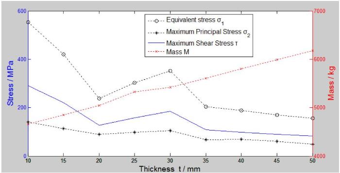
It can be seen from Figure 5 that univariate analysis results of stiffeners’ thickness show that the mass increases approximately linearly as the thickness increases. When the thickness range of stiffeners varies from 10mm to 20mm, the values of the equivalent stress value${{\sigma }_{1}}$, the maximum principal stress value ${{\sigma }_{2}}$, and the maximum shear stress $\tau $decrease greatly as the thickness increases. When the thickness range of stiffeners varies from 20mm to 30mm, the values of the equivalent stress value${{\sigma }_{1}}$, the maximum principal stress value ${{\sigma }_{2}}$, and the maximum shear stress increase to different degreesas the thickness increases. The aforementioned results are not what we would expect. When the thickness of the stiffeners is increased from 35mm to 50mm, the curves of stress value tend to be gentle. Accordingly, it is reasonable to take the thickness near 20mm, which will be utilized to conduct the response surface design.
Figure 5.
The variation of respond values with thickness
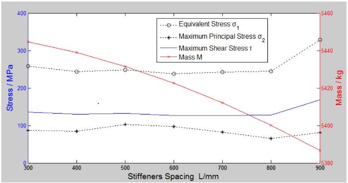
The variation of all the stress values and mass with an increase in spacing between two stiffeners is shown in Figure 6. It can be seen that the mass decreases as the spacing increases. The reason is that the wider the spacing, the shorter the stiffeners, because the pouring cylinder cover is ellipsoidal. However, the variation of each stress value is different. When the size of spacing is less than 800mm, i.e., from 300mm to 800mm, there is only little variation for stress as the spacing between stiffeners increases, but in the range of spacing from 800mm to 900mm, all the stresses increase as the spacing increases, and these results are unexpected. Accordingly, it is reasonable to take the spacing sizeas less than 800mm for response surface design.
The BBD test is performed according to the data listed in Table 3. The test data are obtained by 3-factor 2 level response surface design and are shown in Table 4.
Response surface methodology adopts a set of mathematical and statistical techniques to develop a functional relationship between the response and some input variables. It utilizes the design of experiments to determine the variables influencing the response, and then a response surface can be fitted to quantify relationships between the response and variables [14].
According to the experimental design data of BBD listed in Table 4, Design-Expert software is applied to build the response surface model by using multiple sets of sampling points and response values of the experimental design. Based on the linear regression model and fitting function, the fitting function of each response value is obtained as Equations(2)-(5).
Where ${{y}_{1}}-{{y}_{4}}$ are the equivalent stress $\sigma $, the maximum shear stress $\tau $, the mass M, and the deformation ∆, respectively. By using Design-Expert software, the fitness of each response function isobtained andlisted in Table 5.
According to [15], it is approximately credible when ${{R}^{2}}>0.8$. In addition,it is very credible in the general engineering application when ${{R}^{2}}>0.95$. The correction fitting degree ${{R}^{2}}$ (Adaj) and prediction fitting degree ${{R}^{2}}$(Pred) are closer, resulting inbetter results. It is considered that the model’s fitting is better when the value of Adeq Precision is larger than 4 [6]. Therefore, according to the values listed in Table 5, the fitting accuracy of the fitting function is reasonable.
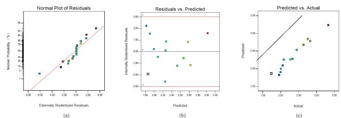
In addition, the residual correlation curve is obtained by Design-expert software to verify the adaptability of the pouring cylinder cover model.
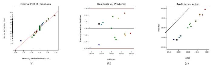
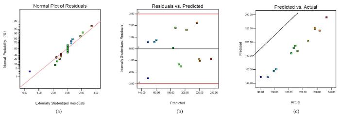
The normal plot of residuals, graph of residual and equation prediction, diagram of actual and predicted values of equivalent stress, maximum shear stress, and deformation are obtained by Design-Export software. If the model has good adaptability, the normal plot of residuals is better when it is closer to the line. For the discrete point of the graph of residual and equation prediction, the more dispersed and irregular the distribution, the better. For the diagram of actual and predicted values, the closer a point is to the line, the better. As can be seen from Figures 7-9, the response surface method is used to fit the pouring cylinder cover model with good adaptability.
Figure 7.
(a)The normal plot of residuals of equivalent stress; (b) The residual and equation prediction of equivalent stress;(c) The actual and predicted value of equivalent stress
Figure 8.
(a) The normal plot of residuals of maximum shear stress;(b)The residual and equation prediction of maximum shear stress;(c)The actual and predicted value of maximum shear stress
Figure 9.
(a) The normal plot of residuals of deformation;(b)The residual and equation prediction of deformation;(c)The actual and predicted value of deformation
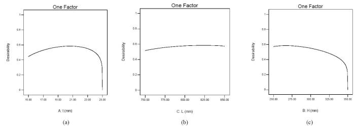
According to the desirability of the pouring cylinder cover obtained by design-expert software, the range of optimal values for each design variable is determined. The higher the value of the ordinate representing desirability, the better the value of the design variable. As shown in Figure 10, the range of optimal values for the thickness t is 19mm ~ 23mm. The range of optimal values for spacing L is 800mm ~ 825mm, and the range of optimal values for height H is 250mm ~ 275mm. The final optimal value is obtained through optimization solution.
Figure 10.
(a)The value range of thickness; (b) The value range of spacing;(c)The value range of height
5. Optimization Results
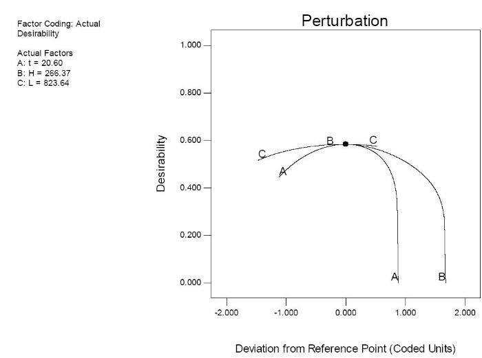
The optimal values of the project are obtained according to the design variables and response values, as shown in Figure 11. The optimized sizes of stiffeners of the cylinder-cover are listed in Table 6.
The optimal values of each design variable are obtained by optimization within the range of single-factor design variables, which indicates that the test results are reliable.
In the engineering application, the optimal data should be rounded to the project value. The principle of rounding is to round up the parameters to increase the strength of the pressure shell [6]. Table 7 shows the final values of structural parameters after rounding.
Table 7
Table 7.The final values of response surface design variables
A method of combining response surface methodology with FEMis utilized, and the influences and optimal size values of stiffeners added on the improved pouring cylinder cover are studied. A multi-objective function is built,and narrowing the ranges of variables isa critical process to solve the multi-parameter structural optimization problem of the improved two-engine cylinder cover with higher accuracy and speed.
Based on the fit functions obtained by using Design-Expert software, a high credible multi-objective optimization problem has been formulated, in which all the response values can be optimized simultaneously. It is practically proven that these optimal sizes’ values are feasible.
Acknowledgments
This work was financially supported by Inner Mongolia Astronautics HongXia Chemical Co.Ltd.
In this study, we proposed a minimum weight design of a submarine pressure hull under hydrostatic pressure with constraints on factors such as general instability, buckling of shell between frames, plate yielding, and frame yielding. A typical submarine pressure hull is also adopted for a prototype model. This design problem is not only formulated as a discrete nonlinear, nondifferentiable, multimodal constrained minimization problem, but also solved by using the backtrack programming method. Results in this study indicate that the solution for the optimal model's weight reduces an average 6.65% more than the prototype model. The process in this study is favorable for the submersible pressure hull design process.
B. W.Song, Q. F.Zhu, P.Wang,
“Research on Optimal Design of UUV Pressure Shell based on Combined Design Method,”
Chinese Journal of Mechanical Science and Technology for Aerospace Engineering, Vol. 29, No. 5, pp.561-565, May 2010
T.Xu, Y.Cheng, Y. M.Ran,
“Analysis and Structural Optimization of Low Temperature Deformation of Axial Piston Pump Shell,”
Chinese Journal of Pneumatic Pneumatics and Seals, Vol. 37, No. 12, pp.5-8, December 2017
X. J.Yang,
“Finite Element Analysis of Bag Filter Case based on ANSYS,”
Chinese Journal of Shanxi Architecture, Vol. 43, No. 28, pp.204-205, October 2017
“Minimum Weight Design of Submersible Pressure Hull under Hydrostatic Pressure”
1
1997
... Structural optimization of pressure hulls has beenthoroughly studied by many researchers, and some useful optimization design methods have been reported [1-4]. Yang et al. [5] provided some optimization methods applied on the pressure hull structure of underwater robot, which can be categorized into two kinds: 1) Experiment method: the capacitor chips are used to measure multi-point stress values of different test samples to obtain the stress distribution and its variation and then determine the variable parameters of optimization according to the stress curve of structure. This method is suitable for solving the optimization problem with less variables and less groups of experiments. 2) Finite Element Analysis (FEA) method: the finite element analysis software is used to simulate the response of structural strength and stability response of different design variables, and the response function, that is, the optimal mathematical model,is obtained. The optimal mathematical model is solved by using optimization theory to obtain the better optimization result. The FEA method cannot be limited by the number of design variables, the cost is lower, and it is ordinarily used to complete preliminary optimization design before the physical test [6]. With respect to the lightweight design of gearbox based on topology optimization, Shen et al. [7] took the minimum flexibility of the gearbox as the objective function and adopted the variable density method to realize the transmission topology optimization to remove some of the reinforcement materials and carry out the rib reinforcement. Hu et al. [5] determined design variables using the screening experimental design based on the response surface method in the robust reliability design. The response surface model was established by using the center combination experimental design method. Li [8] proposed a basic idea of the response surface method to utilize in the research on the response surface method of reliability analysis.Specifically, the explicit simple function instead of the implicit structure function was utilized to conduct reliability analysis. ...
“Research on Optimal Design of UUV Pressure Shell based on Combined Design Method,”
0
2010
“Analysis and Structural Optimization of Low Temperature Deformation of Axial Piston Pump Shell,”
0
2017
“Finite Element Analysis of Bag Filter Case based on ANSYS,”
1
2017
... Structural optimization of pressure hulls has beenthoroughly studied by many researchers, and some useful optimization design methods have been reported [1-4]. Yang et al. [5] provided some optimization methods applied on the pressure hull structure of underwater robot, which can be categorized into two kinds: 1) Experiment method: the capacitor chips are used to measure multi-point stress values of different test samples to obtain the stress distribution and its variation and then determine the variable parameters of optimization according to the stress curve of structure. This method is suitable for solving the optimization problem with less variables and less groups of experiments. 2) Finite Element Analysis (FEA) method: the finite element analysis software is used to simulate the response of structural strength and stability response of different design variables, and the response function, that is, the optimal mathematical model,is obtained. The optimal mathematical model is solved by using optimization theory to obtain the better optimization result. The FEA method cannot be limited by the number of design variables, the cost is lower, and it is ordinarily used to complete preliminary optimization design before the physical test [6]. With respect to the lightweight design of gearbox based on topology optimization, Shen et al. [7] took the minimum flexibility of the gearbox as the objective function and adopted the variable density method to realize the transmission topology optimization to remove some of the reinforcement materials and carry out the rib reinforcement. Hu et al. [5] determined design variables using the screening experimental design based on the response surface method in the robust reliability design. The response surface model was established by using the center combination experimental design method. Li [8] proposed a basic idea of the response surface method to utilize in the research on the response surface method of reliability analysis.Specifically, the explicit simple function instead of the implicit structure function was utilized to conduct reliability analysis. ...
“Reliability Robust Design of Micromanipulation Platform based on Response Surface Method,”
2
2017
... Structural optimization of pressure hulls has beenthoroughly studied by many researchers, and some useful optimization design methods have been reported [1-4]. Yang et al. [5] provided some optimization methods applied on the pressure hull structure of underwater robot, which can be categorized into two kinds: 1) Experiment method: the capacitor chips are used to measure multi-point stress values of different test samples to obtain the stress distribution and its variation and then determine the variable parameters of optimization according to the stress curve of structure. This method is suitable for solving the optimization problem with less variables and less groups of experiments. 2) Finite Element Analysis (FEA) method: the finite element analysis software is used to simulate the response of structural strength and stability response of different design variables, and the response function, that is, the optimal mathematical model,is obtained. The optimal mathematical model is solved by using optimization theory to obtain the better optimization result. The FEA method cannot be limited by the number of design variables, the cost is lower, and it is ordinarily used to complete preliminary optimization design before the physical test [6]. With respect to the lightweight design of gearbox based on topology optimization, Shen et al. [7] took the minimum flexibility of the gearbox as the objective function and adopted the variable density method to realize the transmission topology optimization to remove some of the reinforcement materials and carry out the rib reinforcement. Hu et al. [5] determined design variables using the screening experimental design based on the response surface method in the robust reliability design. The response surface model was established by using the center combination experimental design method. Li [8] proposed a basic idea of the response surface method to utilize in the research on the response surface method of reliability analysis.Specifically, the explicit simple function instead of the implicit structure function was utilized to conduct reliability analysis. ...
... ] took the minimum flexibility of the gearbox as the objective function and adopted the variable density method to realize the transmission topology optimization to remove some of the reinforcement materials and carry out the rib reinforcement. Hu et al. [5] determined design variables using the screening experimental design based on the response surface method in the robust reliability design. The response surface model was established by using the center combination experimental design method. Li [8] proposed a basic idea of the response surface method to utilize in the research on the response surface method of reliability analysis.Specifically, the explicit simple function instead of the implicit structure function was utilized to conduct reliability analysis. ...
“Optimization of Underwater Robot Shell Structure,”
4
2016
... Structural optimization of pressure hulls has beenthoroughly studied by many researchers, and some useful optimization design methods have been reported [1-4]. Yang et al. [5] provided some optimization methods applied on the pressure hull structure of underwater robot, which can be categorized into two kinds: 1) Experiment method: the capacitor chips are used to measure multi-point stress values of different test samples to obtain the stress distribution and its variation and then determine the variable parameters of optimization according to the stress curve of structure. This method is suitable for solving the optimization problem with less variables and less groups of experiments. 2) Finite Element Analysis (FEA) method: the finite element analysis software is used to simulate the response of structural strength and stability response of different design variables, and the response function, that is, the optimal mathematical model,is obtained. The optimal mathematical model is solved by using optimization theory to obtain the better optimization result. The FEA method cannot be limited by the number of design variables, the cost is lower, and it is ordinarily used to complete preliminary optimization design before the physical test [6]. With respect to the lightweight design of gearbox based on topology optimization, Shen et al. [7] took the minimum flexibility of the gearbox as the objective function and adopted the variable density method to realize the transmission topology optimization to remove some of the reinforcement materials and carry out the rib reinforcement. Hu et al. [5] determined design variables using the screening experimental design based on the response surface method in the robust reliability design. The response surface model was established by using the center combination experimental design method. Li [8] proposed a basic idea of the response surface method to utilize in the research on the response surface method of reliability analysis.Specifically, the explicit simple function instead of the implicit structure function was utilized to conduct reliability analysis. ...
... Common design methods of response surface testsinclude the central combination experimental design method, the Box-Behnkendesign (BBD) method, and the optimized experimental design method [6]. The design variables about stiffener sizes of cylinder covers are designed by 3 factor 2 level design test by adopting the BBDtest design method. Due to the wider ranges of design variables, if the 3 factor 2 level response surface test is designed directly, it will not only increase the number of tests, but also reduce the optimization accuracy. Therefore, the central combination test method is used to carry out the single factor analysis of different factors to narrow the ranges of each variable, and the values are taken in the vicinity zones of the optimal response value of each factor to the objective function, which effectively reduces the number of tests and improves the accuracy of tests. ...
... According to [15], it is approximately credible when ${{R}^{2}}>0.8$. In addition,it is very credible in the general engineering applicationwhen ${{R}^{2}}>0.95$. The correction fitting degree ${{R}^{2}}$ (Adaj) and prediction fitting degree ${{R}^{2}}$(Pred) are closer, resulting inbetter results. It is considered that the model’s fitting is better when the value of Adeq Precision is larger than 4 [6]. Therefore, according to the values listed in Table 5, the fitting accuracy of the fitting function is reasonable. ...
... In the engineering application, the optimal data should be rounded to the project value. The principle of rounding is to round up the parameters to increase the strength of the pressure shell [6]. Table 7 shows the final values of structural parameters after rounding. ...
“Lightweight Design of Gearbox Housing based on Topological Optimization,”
1
2018
... Structural optimization of pressure hulls has beenthoroughly studied by many researchers, and some useful optimization design methods have been reported [1-4]. Yang et al. [5] provided some optimization methods applied on the pressure hull structure of underwater robot, which can be categorized into two kinds: 1) Experiment method: the capacitor chips are used to measure multi-point stress values of different test samples to obtain the stress distribution and its variation and then determine the variable parameters of optimization according to the stress curve of structure. This method is suitable for solving the optimization problem with less variables and less groups of experiments. 2) Finite Element Analysis (FEA) method: the finite element analysis software is used to simulate the response of structural strength and stability response of different design variables, and the response function, that is, the optimal mathematical model,is obtained. The optimal mathematical model is solved by using optimization theory to obtain the better optimization result. The FEA method cannot be limited by the number of design variables, the cost is lower, and it is ordinarily used to complete preliminary optimization design before the physical test [6]. With respect to the lightweight design of gearbox based on topology optimization, Shen et al. [7] took the minimum flexibility of the gearbox as the objective function and adopted the variable density method to realize the transmission topology optimization to remove some of the reinforcement materials and carry out the rib reinforcement. Hu et al. [5] determined design variables using the screening experimental design based on the response surface method in the robust reliability design. The response surface model was established by using the center combination experimental design method. Li [8] proposed a basic idea of the response surface method to utilize in the research on the response surface method of reliability analysis.Specifically, the explicit simple function instead of the implicit structure function was utilized to conduct reliability analysis. ...
“Research on Reliability Analysis of Response Surface Method,” Dissertation of Chongqing University,
1
2016
... Structural optimization of pressure hulls has beenthoroughly studied by many researchers, and some useful optimization design methods have been reported [1-4]. Yang et al. [5] provided some optimization methods applied on the pressure hull structure of underwater robot, which can be categorized into two kinds: 1) Experiment method: the capacitor chips are used to measure multi-point stress values of different test samples to obtain the stress distribution and its variation and then determine the variable parameters of optimization according to the stress curve of structure. This method is suitable for solving the optimization problem with less variables and less groups of experiments. 2) Finite Element Analysis (FEA) method: the finite element analysis software is used to simulate the response of structural strength and stability response of different design variables, and the response function, that is, the optimal mathematical model,is obtained. The optimal mathematical model is solved by using optimization theory to obtain the better optimization result. The FEA method cannot be limited by the number of design variables, the cost is lower, and it is ordinarily used to complete preliminary optimization design before the physical test [6]. With respect to the lightweight design of gearbox based on topology optimization, Shen et al. [7] took the minimum flexibility of the gearbox as the objective function and adopted the variable density method to realize the transmission topology optimization to remove some of the reinforcement materials and carry out the rib reinforcement. Hu et al. [5] determined design variables using the screening experimental design based on the response surface method in the robust reliability design. The response surface model was established by using the center combination experimental design method. Li [8] proposed a basic idea of the response surface method to utilize in the research on the response surface method of reliability analysis.Specifically, the explicit simple function instead of the implicit structure function was utilized to conduct reliability analysis. ...
“On the Experimental Attainment of Optimum Conditions,”
1
1951
... Recently, the response surface methodology has been adopted to optimize the structure of the two-engine pouring cylinder cover. Response surface methodology (RSM) is an experimental design method that was proposed by Box et al. [9], and it is widely used in various fields.RSM is also an optimization method for comprehensive test design and mathematical modeling. Through design experiments, sample points are selected for testing, the function relationship between variables and results is simulated by regression, and the optimal level of each variable is obtained [10]. The response surface method is used to approximate the real response surface by fitting the response value of the sample points in the specified design space. In engineering optimization design, the response surface method can not only obtain the change relation between the response target and design variable, but also obtain the optimization scheme, i.e., the optimal combination of design variables, so as to achieve the optimal objective function. The response surface method has the advantages of low test times, high precision, high precision of the regression equation, good prediction performance, and the ability to study the interaction between several factors[11-12]. Jiang et al. [13] proposed a set of slope system reliability analysis methods based on the stochastic response surface method in slope system reliability analysis. The representative sliding surfaces were selected from a large number of potential sliding surfaces. ...
“Statistical Design and Analysis of Experiments with Applications to Engineering and Science,” John Wiley and Sons Publication,
1
2003
... Recently, the response surface methodology has been adopted to optimize the structure of the two-engine pouring cylinder cover. Response surface methodology (RSM) is an experimental design method that was proposed by Box et al. [9], and it is widely used in various fields.RSM is also an optimization method for comprehensive test design and mathematical modeling. Through design experiments, sample points are selected for testing, the function relationship between variables and results is simulated by regression, and the optimal level of each variable is obtained [10]. The response surface method is used to approximate the real response surface by fitting the response value of the sample points in the specified design space. In engineering optimization design, the response surface method can not only obtain the change relation between the response target and design variable, but also obtain the optimization scheme, i.e., the optimal combination of design variables, so as to achieve the optimal objective function. The response surface method has the advantages of low test times, high precision, high precision of the regression equation, good prediction performance, and the ability to study the interaction between several factors[11-12]. Jiang et al. [13] proposed a set of slope system reliability analysis methods based on the stochastic response surface method in slope system reliability analysis. The representative sliding surfaces were selected from a large number of potential sliding surfaces. ...
“Application of Response Surface Method in Experimental Design and Optimization,”
1
2015
... Recently, the response surface methodology has been adopted to optimize the structure of the two-engine pouring cylinder cover. Response surface methodology (RSM) is an experimental design method that was proposed by Box et al. [9], and it is widely used in various fields.RSM is also an optimization method for comprehensive test design and mathematical modeling. Through design experiments, sample points are selected for testing, the function relationship between variables and results is simulated by regression, and the optimal level of each variable is obtained [10]. The response surface method is used to approximate the real response surface by fitting the response value of the sample points in the specified design space. In engineering optimization design, the response surface method can not only obtain the change relation between the response target and design variable, but also obtain the optimization scheme, i.e., the optimal combination of design variables, so as to achieve the optimal objective function. The response surface method has the advantages of low test times, high precision, high precision of the regression equation, good prediction performance, and the ability to study the interaction between several factors[11-12]. Jiang et al. [13] proposed a set of slope system reliability analysis methods based on the stochastic response surface method in slope system reliability analysis. The representative sliding surfaces were selected from a large number of potential sliding surfaces. ...
“Cultivation of Edible Fungi,”
1
2002
... Recently, the response surface methodology has been adopted to optimize the structure of the two-engine pouring cylinder cover. Response surface methodology (RSM) is an experimental design method that was proposed by Box et al. [9], and it is widely used in various fields.RSM is also an optimization method for comprehensive test design and mathematical modeling. Through design experiments, sample points are selected for testing, the function relationship between variables and results is simulated by regression, and the optimal level of each variable is obtained [10]. The response surface method is used to approximate the real response surface by fitting the response value of the sample points in the specified design space. In engineering optimization design, the response surface method can not only obtain the change relation between the response target and design variable, but also obtain the optimization scheme, i.e., the optimal combination of design variables, so as to achieve the optimal objective function. The response surface method has the advantages of low test times, high precision, high precision of the regression equation, good prediction performance, and the ability to study the interaction between several factors[11-12]. Jiang et al. [13] proposed a set of slope system reliability analysis methods based on the stochastic response surface method in slope system reliability analysis. The representative sliding surfaces were selected from a large number of potential sliding surfaces. ...
“Reliability Analysis of Slope System based on Stochastic Response Surface Method,”
1
2015
... Recently, the response surface methodology has been adopted to optimize the structure of the two-engine pouring cylinder cover. Response surface methodology (RSM) is an experimental design method that was proposed by Box et al. [9], and it is widely used in various fields.RSM is also an optimization method for comprehensive test design and mathematical modeling. Through design experiments, sample points are selected for testing, the function relationship between variables and results is simulated by regression, and the optimal level of each variable is obtained [10]. The response surface method is used to approximate the real response surface by fitting the response value of the sample points in the specified design space. In engineering optimization design, the response surface method can not only obtain the change relation between the response target and design variable, but also obtain the optimization scheme, i.e., the optimal combination of design variables, so as to achieve the optimal objective function. The response surface method has the advantages of low test times, high precision, high precision of the regression equation, good prediction performance, and the ability to study the interaction between several factors[11-12]. Jiang et al. [13] proposed a set of slope system reliability analysis methods based on the stochastic response surface method in slope system reliability analysis. The representative sliding surfaces were selected from a large number of potential sliding surfaces. ...
“Optimization of Geometric Parameters in a Welded Joint Through Response Surface Methodology,”
1
2017
... Response surface methodology adopts a set of mathematical and statistical techniques to develop a functional relationship between the response and some input variables. It utilizes the design of experiments to determine the variables influencing the response, and then a response surface can be fitted to quantify relationships between the response and variables [14]. ...
“The Improved Response Surface Method and its Application to Engineering,”
1
2011
... According to [15], it is approximately credible when ${{R}^{2}}>0.8$. In addition,it is very credible in the general engineering applicationwhen ${{R}^{2}}>0.95$. The correction fitting degree ${{R}^{2}}$ (Adaj) and prediction fitting degree ${{R}^{2}}$(Pred) are closer, resulting inbetter results. It is considered that the model’s fitting is better when the value of Adeq Precision is larger than 4 [6]. Therefore, according to the values listed in Table 5, the fitting accuracy of the fitting function is reasonable. ...


