


1. Introduction
Wind energy is the fastest growing renewable energy technology. The technology is relatively mature, and it is a widely promoted and commercialized energy industry. China's wind energy reserves are at the forefront of the world, and their distribution area is relatively wide. The distribution of wind farms in Guangdong, Hunan and North China to the Inner Mongolia Autonomous Region and Heilongjiang Province in the south covers a large area with a wide operating temperature. The reliability of the lubrication system is especially significant important. In recent years, large-scale wind turbines have become the developmental trend of high-power wind turbines. The operation of the gearbox needs to withstand greater load on the stability of the lubrication system. The continuous accumulation of lubrication system failure occurs from time to time, reducing the efficiency of the unit and seriously affecting the economic benefits of wind farm owners [1]. According to the "Report on the Operation Quality of Wind Power Equipment in China," the gearbox is a key component of frequent faults. Lubrication system failure is the main type of gearbox in the type of fault that has been identified, and the proportion of lubrication system failure increases year by year. However, the corresponding gearbox lubrication technology is still not perfect [2]. Therefore, it is necessary to systematically summarize the faults of the wind turbine gearbox lubrication system and to establish the fault tree of the gearbox lubrication system. Based on the analysis of the fault tree of the lubrication system, a corresponding solution to the common fault types is proposed after the lubrication system design for reference.
2. Wind Turbine Lubrication System Overview
Wind turbine gearbox lubrication using splash lubrication and forced lubrication combination of lubrication is shown in Figure 1.
Figure 1.
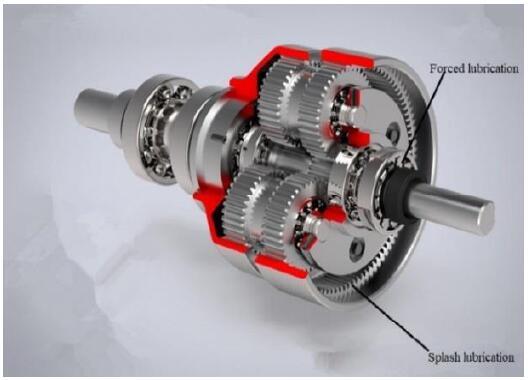
Figure 1.
Gear boxlubrication
Splash lubrication is the use of gear box operation of the main shaft gear and planetary gear and other pieces of movement. The lubrication of splash lubrication varies with the speed of the gear box. The faster the gear rotates, the greater the lubrication is. Therefore, the lubrication effect is worse when the gear speed is slower. Due to the larger torque transmitted by the main shaft of the wind generator, there is a need to increase the force lubrication system to ensure lubrication [3].
Table 1. The forced lubrication system
| Components of the lubrication system | Main function | Effect of failure |
|---|---|---|
| Oil storage device | Store lubricating oil | Lube oil leakage |
| Oil supply device | Pressurization for lubricating oil | Low oil pressure in lubricating system |
| Filter device | Remove impurities from lubricating oil | Excessive impurities in lubricating oil aggravate the wear of moving parts |
| Cooling and heating device | Maintain the normal working temperature of the lubricating oil | Oil temperature anomaly |
| Lubricating line | For conveying lubricating oil | Oil pressure anomaly, lubricating oil leakage |
| Sensor | Testing lubrication system | System misreport |
3. Wind Turbine Lubrication System Common Fault Analysis
According to the working principle and working status of the wind turbine lubrication system, the common faults of the wind turbine gearbox lubrication systemare analyzed, which is helpful to find the deficiencies of the lubrication system and address them.
3.1. Abnormal Temperature of Oil
From the operating condition of the wind farm feedback unit, the wind turbine lubrication system often fails because of the abnormal oil temperature. The abnormal oil temperature can be embodied in two cases, which are too high oil temperature and too low oil temperature. The following reasons for high oil temperature and low oil temperature are analyzed.
The main cause of excessive oil temperature is the long and full load operation of the gear box, the damage of the gear box components, and the insufficient capacity of the cooling system. The heat source of the lubricating oil is the heat produced by the bearing and the gear in the gear box. When the heat is not dispersed well, the temperature of the gearbox becomes uncontrollably high [5].
The main reason for low oil temperature is that the temperature of the environment is too low. Wind turbinesare generally set up on mountains, open fields, high altitudes, and high speed areas in order to obtain higher wind speeds.The area year-round temperature is low, which causes winds to greatly influence the engine lubricating system. There is a need for a lubricating oil heating system to heat the lubricating oil in advance, so as to reach the working temperature. If a fault occurs in the lubricating oil heating system, it will lead to the oil temperature being too low, reduce the lubrication effect, and increase the burden on the oil supply system to improvethe reliability of wind turbines [6].
3.2. Oil Pressure Anomaly
Oil pressure anomaly is one of the main faults of wind generator lubrication systems. If oil pressure is too high, there will be a risk of pipeline rupture. This will cause great pressure on the oil pump and can easily lead to mechanical failure, resulting in downtime. Low oil pressure is very difficult to ensure the thickness of the oil film, reducing the lubrication effect and affecting the efficiency of the lubrication system.
The causes of high pressure are as follows: excessive impurities in the lubricating oil pipeline lead to oil pipeline blockage, which will increasethe pressure in the filter pipeline; the bypass valve does not open or opens only a small volume, which leads to the front end of the filter pressure circuit increasing; the lubricating oil viscosity is too high, resulting inhigh oil pressure in the mechanical gear pump and gear pump oil outlet [7].
The main reasons for low oil pressure are as follows: abnormal work of the oil supply system, the leakage of lubricating oil, and the low viscosity of the lubricating oil.
The abnormal performance of the oil supply system involves the two aspects of mechanical pump failure and electric pump failure.
The mechanical pump is driven by the spindle of the gear box. It may be mechanically damaged because of the excessive viscosity of the lubricating oil and the blockage of the oil path. Low level of oil can also cause the oil pumpto not suck in oil or breathe in some air or foam, which can also lead to low oil pressure in the lubricating system. When the wear of the main and passive gear is serious, it will also cause a decreasein the efficiency of the mechanical pump to affect the oil pressure of the lubricating system [8].
The electric pump is powered by the circuit system and drives the motor to drive the oil pump to pressurize the lubrication system. The main faults of the electric pump system are as follows: the overheating of the motor, the overload of the motor, the non-start of the motor, and the noise of the vibration. Due to operating in a closed environment, poor motor cooling can cause motor overheating; electronic component failure or burnout failure can also cause motor overheating; power supply voltage instability can cause the motor temperature to be too high; motor or internal short circuit power circuit breakers will lead to a sharp rise in the temperature of the motor. The electric pump system will also be overloaded because of the abnormal work of the dragged gear pump. If the motor does not start, it may be a power supply system circuit fault. If the oil pressure is too high or there are too many bubbles in the lubricating oil, there will be greater vibration and noise during the process of lubricating oil pressurization.
The reasons for the leakage of the lubricating oil are the aging damage of the seal ring, the improper installation of the pipe joint, and the breakage of the pipeline. When the viscosity of the lubricating oil is too high,or the lubricating oil pipeline is blocked, the oil pressure of the lubricating system or part of the pipeline is too high, which leads to the leakage of the lubricating oil.
When the oil viscosity is too low, the oil pressure at the nozzle is not easy to maintain. When the oil pressure is too low, the thickness of the oil film is not large enough, resulting in excessive wear of the gear box. When the viscosity of the oil is too low, the leakage phenomenon of the lubricating oil will happen more easily, which will affect the reliability of the gearbox.
3.3. Anomaly of Oil Level
Abnormal oil level includes high oil level and low oil level. Excessive lubricating oil may be added to the sensor fault or misoperation, which causes high oil level to affect the stability of the lubrication system. Low oil level is caused when a lack of lubricating oil and high viscosity of lubricating oil result in misinformation of the oil level sensor. The lubricating system may reduce the system oil slowly because of the oil leakage of each part, causing the system oil level to be too low to alarm. When the viscosity of the lubricating oil is too high, the judgment of the oil level sensor will be affected, and the misjudgment of the low oil level causes the shutdown of the wind turbine.
3.4. Poor Oil Quality
The wind power generator in the running process may be rated power long-term work state. The lubrication system oil temperature will rise, increasing the chemical activity of the lubricating oil and air oxidation reaction and greatly reducing the lubrication effect. The filtering system abnormal work will also affect the lubricating oil.When the filter is blockedorthere is high viscosity of lubricating oil from the bypass valve, the impurities in the lubricating oil will not be filtered out. The impurities in the lubricating oil will aggravate the bearings and gears in the gear box. When water enters the lubrication system, the gear is stirring under the lubricating oil emulsification metamorphoses quickly, seriously affecting the reliability of the wind turbine.
According to the common failure analysis of the wind turbine lubrication system, we established the fault tree of the Figure 2 wind turbine lubrication system and took the failure of the wind turbine lubrication system as the top event. Combined with the fault phenomena and the cause of the failure, it provided a basis for troubleshooting and maintaining the wind turbine lubrication system. The fault tree model events are shown in Table 2[9].
Figure 2.
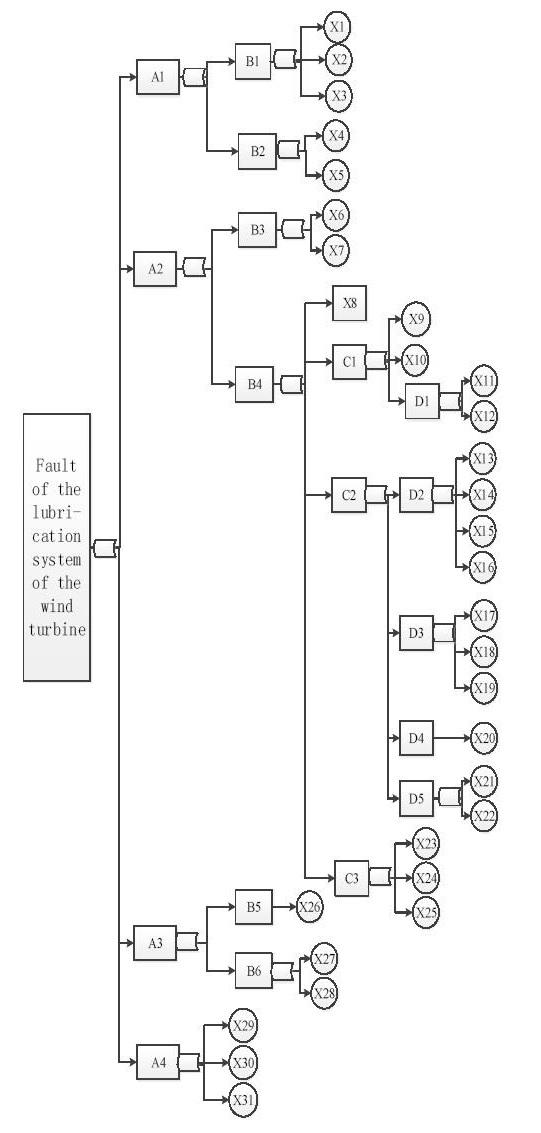
Figure 2.
Fault tree of wind turbine lubrication system
Table 2. Fault tree model event
| Serial number | Event description | Serial number | Event description |
|---|---|---|---|
| A1 | Oil temperature anomaly | X8 | Low viscosity of lubricating oil |
| A2 | Oil pressure anomaly | X9 | Serious wear and tear of the main and passive gear |
| A3 | Anomaly of oil level | X10 | Inhalation of foam or air |
| A4 | Poor oil quality | X11 | Oil road blockage |
| B1 | Oil temperature too high | X12 | High viscosity of lubricating oil |
| B2 | Oil temperature too Low | X13 | Poor heat dissipation |
| B3 | Oil pressure too high | X14 | Electronic component failure |
| B4 | Oil pressure too low | X15 | Power supply voltage anomaly |
| B5 | Oil level too high | X16 | Circuit short circuit or circuit breakage |
| B6 | Oil level too low | X17 | Oil road blockage |
| C1 | Mechanical pump failure | X18 | High viscosity of lubricating oil |
| C2 | Electric pump failure | X19 | Abnormal work of a dragged gear pump |
| C3 | Lube oil leakage | X20 | line fault |
| D1 | Mechanical overload | X21 | Oil pressure too high |
| D2 | Motor overheating | X22 | Overabundance of bubbles in lubricating oil |
| D3 | motor overload | X23 | Seal ring damage |
| D4 | Motor does not start | X24 | Pipe joint loosening |
| D5 | Larger vibration noise | X25 | Lubricating oil pipeline breakage |
| X1 | Long term full load operation | X26 | Overabundance of oil |
| X2 | Gear box component damage | X27 | Insufficient oil |
| X3 | Work anomaly of cooling system | X28 | The viscosity of the lubricating oil is too high to cause misreport |
| X4 | Low ambient temperature | X29 | Long term high temperature lead to lubricating oil |
| X5 | Abnormal heating system of lubricating oil | X30 | Filtering system work exception |
| X6 | High viscosity of lubricating oil | X31 | Lubricating oil modification emulsification |
| X7 | Filter system bypass valve pressure is too high |
Wind turbines generally operate in harsh environments. In the work process, they will face a variety of complex loads. As an example, for a 2.5MW wind generator produced by a domestic company, the cut-in speed is 4m/s, the rated wind speed is 13m/s, and the cut-out speed is 25m/s. However,there are sometimes extreme wind speeds up to 30m/s, and the wind speed in fifteen seconds can be increased from 0m/s to 30m/s in extreme wind conditions. The spindle speed will rise from the normal work of 20r/min to 25r/min or even faster. The spindle speed and torque fluctuation of the bearing become more severe at this time, and it is easy to cause the high temperature of the gear case. Because of its special location, there will be great fluctuations in the temperature range of lubricating oil for the lubricating system during normal operation of the wind, generally at -15℃-65 ℃. When the temperature is too low due to the increase in viscosity of the lubricating oil, a great burden on the oil supply system is liable to cause high oil pressure or mechanical failure of the oil pump, which affects the reliability of the normal operation of the wind turbine[10]. In Figure 3, faults of wind turbine type statistics can be seen.The probability of failure of the lubricating system is very high, and the following problems exist in the lubrication system:The oil temperature of the lubrication system cannot be adjusted adaptively. The lubrication strength of the lubrication system cannot change with spindle speed. The lubrication system filter equipment cannot change accuracy with the oil state.
Figure 3.
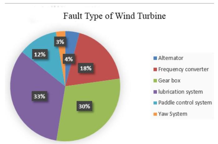
Figure 3.
Fault type of wind turbine
The wind turbine workplace is bad, maintenance is difficult, and maintenance costs are high, which affects the economic benefits of wind farms, so it is necessary to establish an adaptive lubrication system to ensure the normal operation of wind turbines.
4. Adaptive Design of Lubrication System
The self-adaptive lubrication system is intended to introduce an artificial intelligence method that can autonomously analyze internal and external environments [11]. When extreme weather conditions are encountered, it can independently improve the controllable operating environment, optimize its own lubrication status, and ensure that the lubrication system is at high temperature, low temperature, full load, etc. The normal work under special circumstances improves the adaptability of the environment. Compared with the existing lubrication system, the damage can be minimized, the adverse effects of the extreme environment on the lubrication system can be effectively reduced, the gear box of the wind turbine can be adequately lubricated, and the wind turbine’s service life can be extended [12].
4.1. Structural Design of Lubricating System
The adaptive lubrication system mainly includes the oil storage system, oil supply system, filtration system, cooling system, heating system, sensor, solenoid valve, oil circuit, and so on. An adaptive lubrication systemis designed, as shown inFigure 4.
Figure 4.
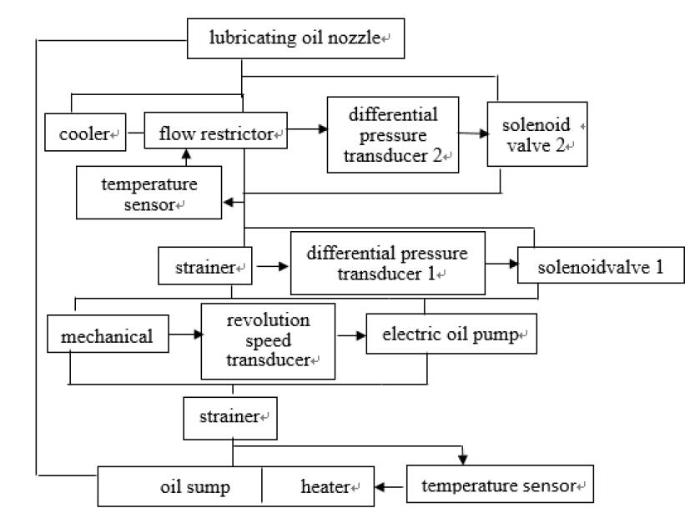
Figure 4.
Adaptive lubrication system—represent oil road→represent signal
4.2. Heat Balance Calculation of Lubricating System
Calculating the heat generation of the gearbox and the cooling of the cooler is the key to designing the lubrication system. When the speed of the wind turbine increases rapidly, the gearbox will generate a large amount of heat. Because the working environment is relatively closed, we believe that the heat generated will be emitted through the cooling system. Therefore, it is very important to determine the power of the cooling system. If the power of the cooling system is too large, it will cause unnecessary workload to the lubrication system. If the cooling system power is too small, the temperature of the gear box will be too high. The following calculation method can provide the heat of the gear box and an accurate calculation of the cooling capacity of the cooling system. It provides scientific guidance for the design of the radiator of the adaptive lubrication system, ensuring that the lubrication system does not overheat when working under extreme conditions, thereby improving the working stability of the lubrication system[13].
The heat generated by the bearing is divided into two parts, the bearing fixed thermal power Pb0 and the thermal power Pb1 varying with the load.
${{v}_{\text{oil}}}$ is the viscosity of the lubricating oil at working temperature. $n$ is the bearing speed (r/min). ${{f}_{0}}$ is the coefficient associated with the form and lubrication of the bearing. ${{d}_{m}}$ is the bearing middle diameter (mm). $\omega$ is the degree of the bearing angular speed (rad/s). The bearing coefficient ${{f}_{0}}$ value is shown in Table 3.
Table 3. Bearing coefficient f0 value table
| Bearing type | Lubricating type | ||
|---|---|---|---|
| Oil mist | Oil bath | Oil jet lubrication | |
| Deep groove ball bearing single row Double row | 1 2 | 2 4 | 4 8 |
The gearbox input shaft bearing speed is slower, ${{v}_{\text{oil}}}\times n<2000\text{m}{{\text{m}}^{2}}/\text{ }\left( s\times min \right)$. The input shaft bearing thermal power calculation formula is selected (1). The generator rated speed is faster, ${{v}_{\text{oil}}}\times n>2000\text{m}{{\text{m}}^{2}}/\text{ }\left( s\times min \right)$, so the output shaft bearing thermal power calculation formula is selected (2).
The formula for calculating the heating power $~{{P}_{b1}}$ with the change of the load is as follows:
${{f}_{1}}$ is the bearing coefficient, and ${{P}_{1}}$ is the dynamic load of the equivalent bearing. Coefficient ${{f}_{1}}$ and the equivalent shaft bearing ${{P}_{1}}$ value are shown in Table 4.
Table 4. Bearing coefficient and equivalent shaft bearing value table
| Bearing type | f1 | P1 |
|---|---|---|
| Deep groove ball bearing | 0.0003(P0/ C0)0.4 | 1.4Y2Fa-0.1Fr |
| Angle contact ball bearing single row Double row | 0.001(P0/ C0)0.33 0.001(P0/ C0)0.33 | Fa-0.1Fr 1.4Y2Fa-0.1Fr |
| P0 is bearing equivalent static load P1 is a bearing equivalent dynamic load C0 is the basic rated static load of the bearing Fa is the axial load of bearing Radial load of Fr bearing If P1<Fr,P1= Fr | ||
To sum up, the power of the single bearing in the gear box is as follows:
The total heat power produced by the work of the bearing in the gearbox is:
The formula for calculating the thermal power of a single gear Pg is:
ha≤mn, f=2.3;ha =(1~1.8)
$P$ is the rated power of the wind turbine gearbox, and $f$ is related to the addendum and the gear method. ${{h}_{a}}$ is the gear tooth height. ${{m}_{n}}$ is a gear normal modulus. ${{z}_{1}}$ and ${{z}_{2}}$ are the number of gear teeth. “+”is for gears, and “-”is for internal gears. $~{{\mu }_{z}}$ is associated with the friction coefficient of the gear, and ${{\mu }_{z}}=1.25\mu $. $\mu$ is the coefficient of friction of gear meshing. The formula used in the classical Buckingham semi-empirical formula is the following:
$v$ is the circumferential speed of the gear.
The relation between the peripheral speed and friction factor is shown inFigure 5.
Figure 5.
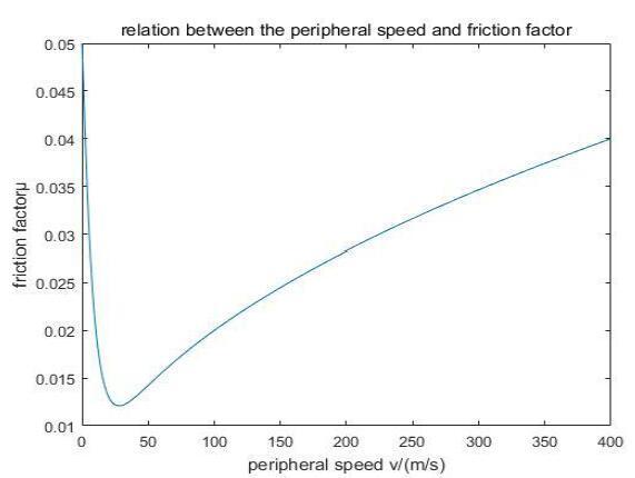
Figure 5.
Relation between the peripheral speed and friction factor
Therefore, the total heat power of the gear box is as follows:
$n$ is the number of gears.
The total heat producing power of the gearbox is:
For the heat dissipation of the lubrication system, we only consider the cooling of the lubricating system cooler. The formula for calculating the heat dissipation power of the radiator ${{P}_{s}}$ is as follows:
$h_{c}$ is the heat transfer coefficient $(W/(m^{2} times K )$, because the heat transfer coefficient of the cooling system of the wind turbine is forced convection, and the heat transfer coefficient is only related to the air velocity. $A$ is the heat transfer area $m^{2}$.
For the cooler, ${{t}_{w}}$ is the temperature of the radiator $~(\text{K})$ and ${{t}_{f}}$ is the intake temperature $~(\text{K})$.
In order to maintain the reliability of the operation of the wind turbine lubrication system and keep the lubricating oil in the normal temperature range, the heat dissipation power must be greater than the heating power, that is, ${{P}_{s}}>P$. Otherwise, the oil temperature of the lubrication system of the wind turbine will be too high [14].
4.3. Control Principle of Adaptive Lubrication System
An adaptive lubrication systemis designed, as shown in Figure 6.
Figure 6.
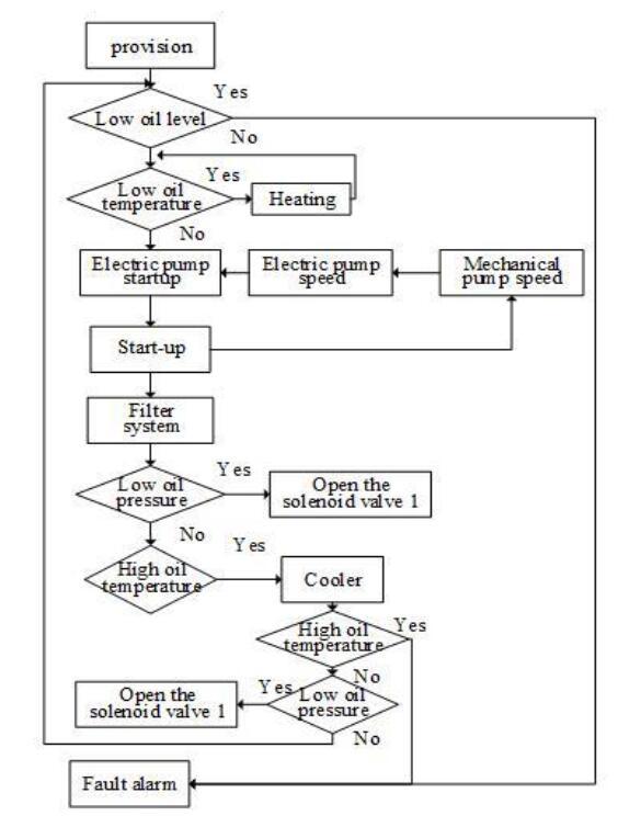
Figure 6.
Lubrication system control chart
In order to prevent the oil pan in the precipitation of impurities, the lubricating oil filter design between the oil supply system of oil pump and oil pan is used to filter large impurities, in order to ensure the strength of the lubrication system can increase with the increasing speed of the gear. The speed sensor is connected in the mechanical pump, collecting the mechanical pump speed and transferring to the electric pump. The electric pump speed can change with the mechanical pump speed due to mechanical power from the spindle, so the power supply system can work as thegear box power increases. The temperature sensor and the lubricating oil in the oil pan heating device in the oil pan side are connected when the oil temperature is too low. The lubricating oil heating device begins to work in parallel. Besides the filter differential pressure sensor, both ends of the oil filter can control the filter parallel electromagnetic bypass valve opening degree when the pressure is too large and add the current limiting valve in parallel with the lubricating oil cooler. Direct fuel injection service occurs if the temperature is normal. There is a high temperature when the electromagnetic valve oil flow is distributed through the cooler. In order to ensure the necessary lubrication effect, the cooler plug installed in the cooler at both ends of the pressure sensor control solenoid opens valve 2.
5. Conclusions
This paper establishes the fault tree of the wind turbine gear box lubrication system. It is pointed out that the incompatibility of lubricating oil temperature, lubrication intensity, and oil state with the working condition of the gear boxare the main factors of frequent failures of the gear box.
The calculation method of the gear box heating power and the cooling power of the cooler are determined, and a theoretical basis is established for the design and maintenance of the wind turbine lubrication system.
By introducing the AI control method, the adaptive lubrication system framework of the wind turbine gear boxis constructed from the aspects of oil temperature, oil pressure, oil level, and oil quality. It can independently adjust the intensity of lubrication, according to the wind turbine work situation. It is also beneficial to improve the lubrication system stability and wind turbine failure-free operation time and decrease the operation and maintenance cost of wind turbines.
Acknowledgments
This work was supported by the National Natural Science Foundation of China (No. 51365031) and the Wind Energy and Solar Energy Utilization Technology, Ministry of Education, Key Laboratory of Ministry of Education, Open Fund (No. 201607).
Reference
“Expert-based FMEA of Wind Turbine System,”
“Failure Modes and Effects Analysis (FMEA) for Wind Turbines”
,
DOI:10.1016/j.ijepes.2010.01.019
URL
[Cited within: 1]

The Failure Modes and Effects Analysis (FMEA) method has been used to study the reliability of many different power generation systems. This paper now applies that method to a wind turbine (WT) system using a proprietary software reliability analysis tool. Comparison is made between the quantitative results of an FMEA and reliability field data from real wind turbine systems and their assemblies. These results are discussed to establish relationships which are useful for future wind turbine designs. The main system studied is an existing design 2 MW wind turbine with a Doubly Fed Induction Generator (DFIG), which is then compared with a hypothetical wind turbine system using the Brushless Doubly Fed Generator (BDFG) of the same rating. The software reliability analysis tool used for these studies was Relex Reliability Studio 2007 Version 2.
“Wind Turbine SCADA Alarm Analysis for Improving Reliability”
,
DOI:10.1002/we.513
URL
[Cited within: 1]
Previous research for detecting incipient wind turbine failures, using condition monitoring algorithms, concentrated on wind turbine Supervisory Control and Data Acquisition (SCADA) signals, such as power output, wind speed and bearing temperatures, using power-curve and temperature relationships. However, very little research effort has been made on wind turbine SCADA alarms. When wind turbines are operating in significantly sized wind farms, these alarm triggers are overwhelming for operators or maintainers alike because of large number occurring in a 1065min SCADA period. This paper considers these alarms originating in two large populations of modern onshore wind turbines over a period of 1–265years. First, an analysis is made on where the alarms originate. Second, a methodology for prioritizing the alarms is adopted from an oil and gas industry standard to show the seriousness of the alarm data volume. Third, two methods of alarm analysis, time-sequence and probability-based, are proposed and demonstrated on the data from one of the wind turbine populations, considering pitch and converter systems with known faults. The results of this work show that alarm data require relatively little storage yet provide rich condition monitoring information. Both the time-sequence and probability-based analysis methods have the potential to rationalize and reduce alarm data, providing valuable fault detection, diagnosis and prognosis from the conditions under which the alarms are generated. These methods should be developed and integrated into an intelligent alarm handling system for wind farms, aimed at improving wind turbine reliability to reduce downtime, increase availability and leading to a well-organized maintenance schedule. Copyright 08 2011 John Wiley & Sons, Ltd.
“Physics of Failure Approach to Wind Turbine Condition Based Maintenance,”
DOI:10.1002/we.360
URL
[Cited within: 1]
Wind turbine condition monitoring systems provide an early indication of component damage, allowing the operator to plan system repair prior to complete failure. However, the resulting cost savings are limited because of the relatively low number of failures that may be detected and the high cost of installing the required measurement equipment. A new approach is proposed for continuous, online calculation of damage accumulation using standard turbine performance parameters and Physics of Failure methodology. The wind turbine system is assessed in order to identify the root cause of critical failure modes and theoretical damage models are developed to describe the relationship between the turbine operating environment, applied loads and the rate at which damage accumulates. Accurate estimates may then be made in real time concerning the probability of failure for specific failure modes and components. The methodology is illustrated for a specific failure mode using a case study of a large wind farm where a significant number of gearbox failures occurred within a short space of time. Such an approach may be implemented at relatively low cost and offers potential for significant improvements in overall wind turbine maintenance strategy. Copyright 2009 John Wiley & Sons, Ltd.
“Seabra. Power Losses at Low Speed in a Gearbox Lubricated with Wind Turbine Gear Oils with Special Focus on Churning Losses,”
DOI:10.1016/j.triboint.2013.02.026
URL
[Cited within: 1]
78 Four wind turbine gear oils were selected. 78 Density and viscosities were measured. 78 Efficiency tests were conducted on a gearbox at low speeds and high torques. 78 Oil flow regimes were identified through thermal equilibrium temperatures analysis. 78 A calibration method for a gear churning loss model is suggested.
Gonalves
,“Torque Loss in a Gearbox Lubricated with Wind Turbine Gear Oils,”
DOI:10.1002/ls.1222
URL
[Cited within: 1]
In this study, four different fully formulated ISO VG 320 wind turbine gear oils were select: a mineral oil-based, a polyalphaolefin-based, an ester-based and a polyalkyleneglycol-based fluids. Their physical properties (viscosity, thermoviscosity, piezoviscosity etc.) were characterised for a wide range of operating temperatures. A two-stage multiplying gearbox, with helical gears, was selected to evaluate the influence of the wind turbine gear oil formulation on torque loss with the gearbox operating at low speed (130230rpm) and high torque (5001000Nm). The results obtained showed that each wind turbine gear oil formulation generated very different torque losses, evacuated heat flows and operating temperatures, with differences above 20 degrees C under the most severe operating conditions. A numerical model was developed, simulating all power loss mechanisms inside the gearbox, in particular the churning and friction losses. The coefficients of friction, between gear teeth and between rolling elements and bearing raceways, were calculated for all the tested oils. Copyright (c) 2013 John Wiley & Sons, Ltd.
“Risk-based Failure Mode and Effect Analysis for Wind Turbine,”
in
“Integrated Analysis of System Reliability and Safety by Man-Machine-Environment System Engineering,”
DOI:10.1007/978-3-642-38968-9_69
URL
[Cited within: 1]
To solve the problem that the efficiency of the traditional system reliability and safety analysis is not high, and the problem that the human factor analysis is usually ignored, an integrated analysis method of reliability and safety based on man-machine-environment system engineering (MMESE) is proposed. This method integrates the system reliability, safety, environment adaptability, and human factor analysis and considers the human factor as the important element of the analysis; thus, the efficiency of the analysis is evidently improved. Finally, this method is applied in the reliability and safety analysis of a shipborne fueling station.
“A Fuzzy Reliability Assessment of Basic Events of Fault Trees Through Qualitative Data Processing,”
DOI:10.1016/j.fss.2013.06.009
URL
[Cited within: 1]
Probabilistic approaches are common in the analysis of reliability of complex engineering systems. However, they require quantitative historical failure data for determining reliability characteristics. In many real-world areas, such as e.g., nuclear engineering, quantitative historical failure data are unavailable or become inadequate and only qualitative data such as expert opinions, which are described in linguistic terms, can be collected and then used to assess system reliability. Moreover, experts are more comfortable justifying event failure likelihood using linguistic terms, which capture uncertainties rather than by expressing judgments in a quantitative manner. New techniques are therefore needed that will help construct models of reliability of complex engineering system without being confined to quantitative historical failure data. The objective of this study is to develop a fuzzy reliability algorithm to effectively generate basic event failure probabilities without reliance on quantitative historical failure data through qualitative data processing. The originality of this study comes with an introduction of linguistic values articulated in terms of component failure possibilities in order to qualitatively assess basic event failure possibilities treated as inputs of the proposed model and generate basic event failure probabilities as its outputs. To demonstrate the feasibility and effectiveness of the proposed algorithm, actual basic event failure probabilities collected from nuclear power plant operating experiences are compared with the failure probabilities generated by the algorithm. The results demonstrate that the proposed fuzzy reliability algorithm arises as a suitable alternative for the probabilistic reliability approach when quantitative historical failure data are unavailable.
“Engineering Systems Reliability, Safety, and Maintenance - An Integrated Approach”
“A New Reliability Analysis Method for Repairable Systems with Closed-Loop Feedback Links”
,
DOI:10.1002/qre.2255
URL
[Cited within: 1]
Abstract A new reliability analysis method for repairable systems with closed-loop feedback link (CLFL) is proposed based on GO methodology. A method for creating new function GO operators is used to describe the CLFL. Next, methods for deducing the formulae of the new GO function are proposed. In addition, a 2-level GO model is proposed for the GO operation of repairable systems with CLFL. And then, quantitative and qualitative analysis methods for repairable systems with CLFL based on the GO method are proposed, and a process for analyzing repairable systems with CLFL based on the new GO method is formulated. Finally, we used this new GO method to analyze the reliability of an electro-hydraulic servo speed control system and a power-shift steering transmission control system for a heavy vehicle. To verify the feasibility, advantages, and reasonability of the new GO method, we compared our results with those obtained by fault tree analysis, Monte Carlo Simulation, and an existing GO method using serial and parallel structures to represent the CLFL. All in all, the proposed method overcomes the limitations of the existing methods as well as increasing its applicability. And it provides a new approach for reliability analysis of repairable systems with CLFL.
“A Hybrid Self-Adaptive Conjugate First Order Reliability Method for Robust Structural Reliability Analysis,”
DOI:10.1016/j.apm.2017.09.017
URL
[Cited within: 1]
The traditional First Order Reliability Method (FORM) using steepest descent search direction may yield unstable solutions due to periodic nature and chaos for reliability analysis problems involving highly nonlinear performance functions. A conjugate search direction approach is attempted in the present study to overcome such problem of the FORM for Most Probable Point (MPP) search. Two iterative FORM schemes are investigated based on conjugate descent direction using self-adaptive conjugate (SAC) and hybrid self- adaptive conjugate (HSAC) search directions for estimating reliability index. The SAC is proposed using Fletcher and Reeves (FR) method and an adaptive conjugate scalar factor to improve the efficiency of the FR method for reliability analysis of highly nonlinear performance function. The HSAC is adaptively computed using FR and SAC methods to improve the robustness and efficiency of the FORM formula. The effectiveness of the proposed SAC and HSAC approaches are studied compare to the traditional FORM algorithms through several numerical examples. The proposed methods based on conjugate search direction are found to be more efficient and robust than the usual FORM algorithms.
“A New Reliability Analysis Method based on the Conjugate Gradient Direction”
,
DOI:10.1007/s00158-014-1113-z
URL
[Cited within: 1]
Reliability-based design optimization (RBDO) is an important area in structural optimization. A principal step of the RBDO process is to solve a reliability analysis problem. This problem has been considered in inner loop of double-loop RBDO approaches. Although many algorithms have been developed for solving this problem, there are still some challenges. Existing algorithms do not have good convergence rates and often diverge. There is a need to develop more efficient and stable algorithms that can be used for evaluating all performance functions sufficiently. In this paper, a new method, called “Conjugate Gradient Analysis (CGA) Method”, is proposed to apply in the reliability analysis problems. This method is based on the conjugate gradient method. Some mathematical problems are provided in order to demonstrate the advantages of the proposed method compared with the existing methods.
“Fuzzy Reliability Analysis of Nonlinear Structural System based on Stochastic Response Surface Method,”
