


1. Introduction
With the rapid development of agriculture and animal husbandry, the baler has gradually become an indispensable and effective tool for the harvest of forage grass and straw. Due to the different development of agricultural mechanization and the different operation and scale of agricultural production, small square balers will remain the mainstream models of square baler machines for the foreseeable future. The D-knotter of Germany ARSSPE Company is a small package of lawn mower key ancillary products, and the performance of each other's bale baler quality and machine tool reliability play a decisive role. Affected by factors such as the quality of the machine, the working environment, and the use and maintenance, the D-knotter often fails prematurely during the actual baling operation, affecting the timely harvest of forage grass and straw and increasing the operation and maintenance costs [1]. Improving the adaptability and reliability of the knotter is an important direction in the development of the knotter.
2. D-Knotter Overview
The D-knotter is a key part of the square bale pick-up baler. The pick-up baler presses the loose pasture placed on the ground into a square bale. The knotter finally kicks the square bale automatically to facilitate handling, transportation, storage, and so on.The D-knotter was developed with the balers, and the first one was manufactured by the United States Deering Agricultural Machinery Company. After continuous improvement, the knotter wasdeveloped into the D-knotter produced in Germany and the United States playing knot quality.
Figure 1.
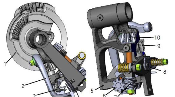
Figure 1.
D-knotter structure
1. Driving gear plate; 2. Casting off rope lever; 3. Knotting mouth; 4.Clamping rope; 5. Frame body; 6. Drive rope clamp worm gear; 7. Worm 8.Upper jaw cam; 9.Knotting hook bevel gear; 10. Worm bevel gear
The D-knotter process is divided into eight steps: (1) lead the rope; (2) dial the rope; (3) clamp the rope; (4) rope around; (5) the upper jaw open; (6) the upper jaw closed; (7) cut the rope; (8) get rid of the rope buckle. By introducing the three-dimensional model of the knotter into the ADAMS software, the virtual knot process is simulated.
The first action is to clamp the rope. When the time is about to reach 0.375s, the outer bevel gear and the bevel gear wheel began to mesh through the worm drive to drive the clamp rope mechanism. When the time reaches about 0.515s, the clamp rope action is completed, as shown in Figure 2.
Figure 2.
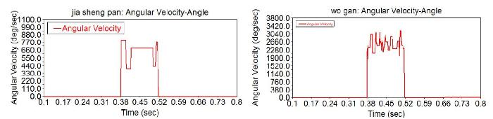
Figure 2.
Timing diagram of worm and clamp rope mechanism
The second action is to around the rope and bite the rope. When the time reaches 0.415s, the inner bevel gear and the gear disk knot jaws gears begin to mesh, driving the knotting forceps mouth around the rope and opening and closing the upper jaw. When the time reaches 0.51s, the upper jaw and knotting forceps mouth finish around the rope and the bite rope, as shown in Figure 3.
Figure 3.

Figure 3.
Timing diagram of the upper jaw and knotting forceps mouth
The third action is to cut the rope and get rid of the rope buckle. When the time reaches about 0.465s, the plate cam of the gear and the wheel of the stripping rod begin to cooperate and through the wheel of stripping rod drives stripping rod cut rope and get rid of the rope buckle. When the time reaches 0.71s, all the action of knotting is basically completed, as shown in Figure 4.
Figure 4.
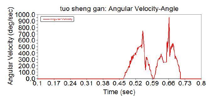
Figure 4.
Timing diagram of stripping rod
By analyzing the knot tying sequence analysis, knot tying can be divided into the above three routes. However, these three actions are not independent. The interrelated knot knotting movement is intermittent coordinated exercise, and each action must be coordinated with other actions. Through the timing analysis of the knotter, it is required that the reliability of each part should be high [3].
3. Failure Type and Failure Mechanism of Knotter
The knotter’s parts will be subjected to a variety of twisting, shearing, cutting, pressing, and other complex forces, coupled with knotting in the field work. The working environment is very poor, so the knotter is easily damaged. Through the statistics of the working environment, the force, and the actual operation of the baler, the main failure modes of the knotter include five parts: the failure of the clamp rope, the failure of the rope around, the failure of the cut rope, the failure of the upper claw, and the failure to get rid of the rope buckle. From Figure 5, we can see that the main parts that cause the failure of these five categories are the drive gear, frame, casting off rope lever, knotting mouth, clamping rope mechanism, bevel gear, cutting the rope knife, and so on. Through Figure 5, we can see that the failure of the gear plate and the failure of the knotter frame are the most important factors for the five failure modes.
Figure 5.
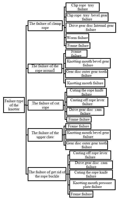
Figure 5.
Failuretypes of the knotter
3.1. Failure Type and Failure Mechanism of the Gear Plate
The main failure type of the driving gear plate is fatigue damage. Compared with the outer gear of the gear plate, though the internal gears are more stressed, the damage of the internal gear of the gear plate is less in the actual working conditions. This is because the internal gear of the driving gear plate is helical gear, which can bear a more excellent load than straight gear.
The damage characteristics of the gear plate and the locking surface are shown in Figures 6 and 7. Some new balers were used in less than a week, and the external gear of the gear plate was already worn out. As a result of the meshing errors caused by the external gear, the jaw bevel gear crushed the locking plane of the gear plate. The gear plate cam is the drive component of the knotter casting off rope lever. The internal cam return and lift of the gear plate are sinusoidal motion law. When the casting off rope lever is about to reach the remote point of the cam, the roller of the casting off rope lever will jump, which will exert a large force on the remote point of the cam and cause the cam to be worn outseriously, as shown in Figure 8.
Figure 6.
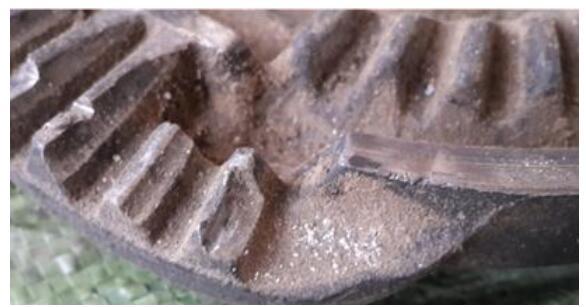
Figure 6.
External gear wear
Figure 7.
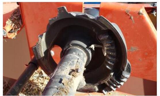
Figure 7.
Damage to the locking surface
Figure 8.
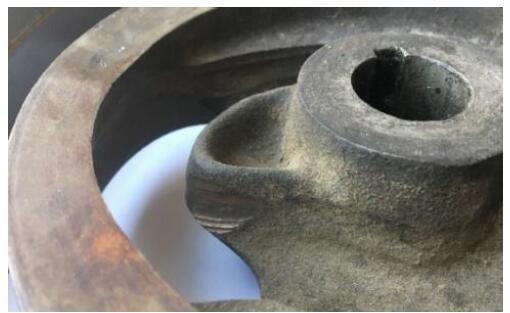
Figure 8.
The gear plate cam wear
3.2. Improvement Measures of the Gear Plate
For the damage characteristics of the gear plate and the locking surface, Ren et al. conducted a static analysis of the knotter driving gear plate and found that the stress concentration part of the driving gear plate is mainly located in the clockwise second root of the internal gear. Therefore, in order to effectively avoid stress concentration, it is suggested that the fillet should be processed at the root of the outer gear when the gear plate is processed [2]. Lu et al. designed a configurable knotter driving gear plate that is bolted together by the internal and external gear and changed the internal gear from helical gear to straight gear, thereby reducing the manufacturing difficulty and processing cost[4].This approach is convenient to replace the two-section gear bar after wear. At present, this design idea has been adopted by Harbin Jinma Agricultural Machinery Parts Manufacturing Co., Ltd. In addition, Zhang et al. designed a double gear plate driving knotter that put the inner and outer gear on the two gear plates, simplifying the space structure, making the machining of thegear more convenient, and reducing the stress of a single gear plate.
In actual production, if the gear plate cam wear is not serious, it can be repaired by surfacing. In view of cam wear, Li et al. optimized the design of a counter weight-driven driver with high surface quality and stable transmission to solve the problem of poor continuity of the cam working surface, static balance, and drive gear wear based on the principle of reverse engineering. Li et al. designed a type of split gear plate mechanism. The cam block and the gear plate main body were connected through the spline and can be easily replaced after the damage. At the same time, three kinds of cam blocks with different types of camber were designed, which can be replaced by different machine types [5]. Li et al. put forward the solution of replacing the existing cylindrical contour with the equal distance circular arc surface of the cam theory profile. The point contact between the convex surface-convex surface and convex surface-plane surface was improved to the arc point contact of the convex surface-concave surface to address the problem of serious wear of the inner contour of the disc cam [6].
3.3. Failure Type and Failure Mechanism of the Frame
The frame body is the most critical part of the D-knotter. In order to accurately knot the knotting action, it is necessary to ensure the positional accuracy of the misaligned shaft holes on the frame body and the precision of controlling the complex surface of the knotting pliers opening and closing [4]. Therefore, the processing requirements of the frame body are very high. During knotting, the frame body is subjected to complicated forces such as twisting, shearing, and cutting. Therefore, the failure modes of the frame body mainly include the frame body breaking, the breaking when cleaning the rope piece stopper, and the wear of five different surface shaft holes.
Fracture is one of the main failure types of the frame, and the general fracture of the frame mainly occurs at the bottom end of the spindle hole and the hole of the worm shaft, as shown in Figure 9. The worm meshes through the worm shaft hole and the teeth in the drive tooth disc. During knotting, the worm shaft hole is the most concentrated part of the stress on the frame [2]. In addition, because the main shaft lubricating oil hole is prone to transverse cracking, lubricating oil often spills there. If the processing is not in time, the spindle will often fail to lubricate, which will result in fracture at the lower end of the spindle. Cleaning the rope piece stopper plays a major role in limiting the clamping rope mechanism, as it can ensure the normal work of the clamping rope mechanism. At the beginning of knotting, firstly, the secondary strapping rope introduced through the baling stitch is pressed on the clear rope piece, and then the internal gear of the chain gear transmits the power to the clamping rope mechanism through the turbine shaft to rotate. The hook-type slot dials the twine to the pressure rope mechanism and the clamping rope mechanism to clamp the rope. Each time the rope is clamped, the clearing rope mechanism will be squeezed. Because of the squeezing force, shaking will occur in the clearing rope mechanism. Because the time is very short, the clearing rope mechanism on the frame body rope stopper block has an impact load moment [7]. Over time, the cleaning the rope piece stopper will be broken.
Figure 9.
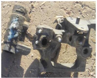
Figure 9.
The lower end of the spindle hole broken
The main parts of the frame are five spatial axial holes, and they ensure not only the shaft hole position accuracybut also the shaft hole surface accuracy. In addition to the processing precision, the main reason is that the lubrication is not timely. The job prone to lubrication is not caused by the shaft hole or the shaft dry friction. In the long run, the shaft hole is worn, as shown in Figure 10. The coordination of each axis is not accurate, leading to knot failure, as shown in Figure 11.
Figure 10.
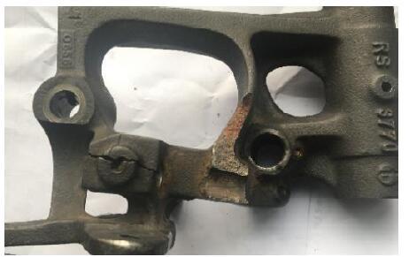
Figure 10.
Frame body worm shaft hole fracture
Figure 11.
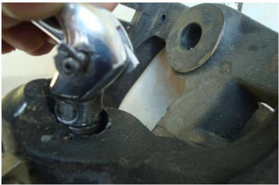
Figure 11.
Wear of the shaft hole
3.4. Improvement Measures of the Frame
The failure of the frame is very important to the knot of the knotter. Many scholars have proposed improvement measures for the failure of the frame [1]. For the frame body failure, Li et al. invented a split knotter, worm shaft hole, and sleeve. As a separate part, the original axis hole position was filled with a solid stiffener to solve the problem thatthe body frame was easy broken. Wang et al. improved the knotting frame. The knotting frame was divided into the main frame and auxiliary frame. The main and auxiliary frames were connected by screws to install on the driving shaft, so that the knot tying device is more quickly and conveniently maintained [8]. Li et al. invented a kind of split type knotter that made the worm shaft hole and shaft sleeve independent of each other. The original shaft hole position was filled with a solid reinforcement to solve the problem that the frame was easily broken and the key parts were dismantled.Ai et al. invented a quick-release knotter body. The knotter power shaft hole was split into two parts to facilitate the installation and maintenance of the knotter. Gao et al. optimized the structure of the frame body, thickened the wall of the worm shaft hole, widened the knot plier holder, and added reinforcing ribs between the two to solve the problem that the frame body was easily broken. Chen et al. invented a mold casting method for the frame, which improved the processing precision of the knot holder. For the Dtype knotter, the secondary bundle rope introduced by the bundling needle was pressed on the wire rope when the knot was started. Then, the worm wheel of the worm wheel drove the rope disc, and the hook type slot of the rope disc moved the tie rope to the connection port of the rope disc and the rope holder. In this process, the wire rope bore an extrusion force and the limit rope clear rope at the same time. The block of the piece produced an instantaneous impact load. Long term work will cause serious wear of the rope and even cause shear failure to the block. In addition, in the process of transportation and installation, the frame sometimes collides with this part of the frame, and it also breaks the block of the rope. In the actual operation, many users weld their own block when the rope block is damaged. After welding, the knotter can still work normally [9]. Wan et al. proposed that since the limit notch of the knotter rope clearing mechanism was machined directly and a right-angled sharp edge was formed,if the notched part was machined into a rounded corner, the stress concentration would be reduced, and thus the knot performance would be improved.
It can be obtained from the knotter principle that the coordination between the various parts of the knotter and the transmission between the parts and the parts should be accurate. Although many scholars have provided a variety of improvements to the failure of the frame, none of them have fundamentally solved the problem of frame failure. The location accuracy and the accuracy of the axle hole surface are the most important factors to ensure the success of knotting knots [10]. Therefore, if we want to solve the problem of the frame failure, we should solve the problem of matching five different shaft holes with each axis on the five sides of the frame. Each shaft hole with the shaft is mainly worn with the deputy, because the frame body shaft hole and the shaft are in direct contact. The knotting lubrication system is manual lubrication. Lubrication often does not occur in time, which leads to serious axial hole wear. The coordination between the shaft hole and the shaft cannot be guaranteed, eventually leading totie failure [11-12]. In view of the problemsof shaft hole and shaft matching, improvements have been made [13-16].
4. The Knotter Reliability Design
Through the comprehensive analysis of knotter frame structure and knot work environment, the final selection of sliding bearings to design is shown. Sliding bearing installation space is particularly low and just in line with the framework of limited space. The general body shaft hole will be lubricated, and knotting device assembly and disassembly are particularly troublesome. Lubrication is particularly troublesome. Maintenance-free lubrication of the sliding bearing has high wear resistance since the bearings are designed with a large number of injection holes. They function as grease reservoirs and continuously release lubricant film so that the lubricant can be dispensed for a long period of time to meet the requirements of the baler in the harvest season. Therefore, the reliability design of the sliding bearing on the assembly of five different surface axle holes is carried out. The knotter spindle speed is 90r/min, the general knotter spindle moment is 45$\text{N}\cdot \text{m}$-100$\text{N}\cdot \text{m}$, the spindle hole diameter is 35mm, and the gear wheel diameter is 220mm.
Through Equations (1) and(2), the maximum spindle gain is 909N.
The above values are brought into the formula for calculation. v is 0.165m/s, P is 0.25MPa, and finally the RCB-092 bronze bearing is selected. As shown in Figure 9, bronze bearing CuSn5.3Pu.3 bronze is the base.
The main failure mechanism of the maintenance free lubrication sliding bearing is the wear of the bearing caused by grease failure. Therefore, the life of the grease is calculated according to the empirical formula of NSK Bearing Company.
T indicates the average lifespan of lubricating grease (h), N indicates the bearing speed (r/min), ${{N}_{\max }}$indicates the limit speed of grease lubrication for bearings specified in the sample(r/min), and T indicates working temperature of bearing (℃).
In Equation(5), the above formula applies to $0.25\le \frac{n}{{{N}_{\max }}}\le 1$, and for the bearing speed n: when $\frac{n}{{{N}_{\max }}}<0.25$, set $\frac{n}{{{N}_{\max }}}=1$. For the bearing operating temperature T: select universal fat:
Set the allowable value of normal wear for a given life of
When the wear amount follows the normal distribution, the reliability coefficient of the bearing is resistant to normal wear.
Where ${{h}_{c}}$, h, and ${{S}_{h}}$ are the average values of the allowable values of normal wear, the average wear and tear, and the standard difference between the actual wear and tear, respectively. Thus, the reliability of sliding bearing resistance to normal wear is
The average value of the actual wear and tear and the standard difference between the actual wear and tear can be obtained in the following way:
In Equation (9), h is the initial clearance, r is the wear speed, and t is the working time.
When h is a normal variable, then
In Equations (10) and (11),${{W}_{\max }}$ and ${{W}_{\min }}$ are the maximum clearance and minimum clearance of the bearings, respectively. When the wear rate r follows the normal distribution,
According to literature, the wear speed of the bearing is
Where the statistical value
According to the references, the allowable value of the normal wear volume is
From literature, the annual wear rate
According to Equations (7) and (8), the reliability coefficient of resistance to normal wear and reliability is 8.77, and the reliability is 0.9863. The knotter work requirements have been reached. The other four different shaft holes on the frame are selected in the same way of calculation. Finally, the bronze bearings of the five kinds of axle holes are assembled on the final frame 5, and the bronze bearings lubricated by lithium grease are shown in Figure 12 and Figure 13.
Figure 12.
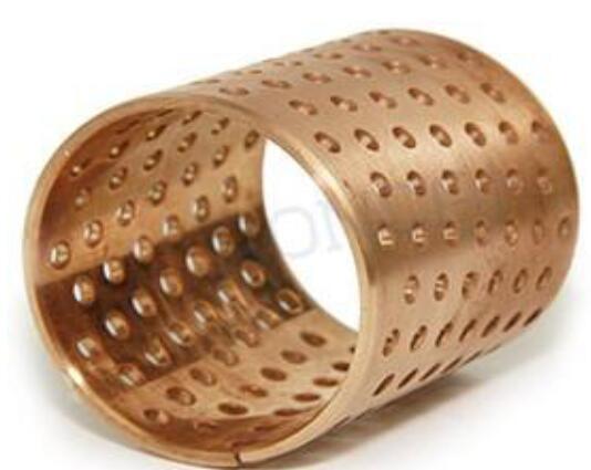
Figure 12.
Bronze sliding bearing
Figure 13.
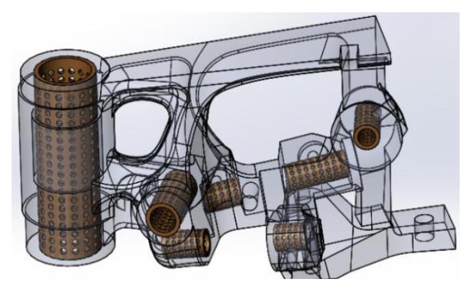
Figure 13.
General assembly drawing
The bearing bore is full of diamond-shaped oil holes. As oil pits, they can store large amounts of grease. With less oil lubrication, they are suitable for situations where it is difficult to refuel or water lubrication is present. They have good wear resistance, a low coefficient of friction, and long service life, which correlate with good performance, low noise, low pollution, and light weight. They also have a thin-walled structure and can reduce the mechanical volume. Therefore, the bronze bearings are designed to meet the needs of knot work.
5. Conclusions
In this paper, the failure modes and failure mechanism of the D-knotter machine were analysed.There are various failure modes of knotting machines, and the failure mechanism is complex. The wear of five different shaft holes on the rack is the root cause of the failure of knotting machines.
The reliability design is carried out for the wear problem of five differentaxis shaft holes. By assembling the bronze bearings lubricated by lithium base grease on the five shaft holes, the shaft hole wear and tear is greatly reduced and the problem of not timely lubrication is solved. Therefore, the reliability of the knotter has been greatly improved.
Acknowledgments
This work is supported by the National Natural Science Foundation of China (No. 51365031) and the National Key Research and Development Project of China (No. 2016YFD0701700).
Reference
“Reconfiguration and Motion Simulation of D Type Knotter based on Reverse Engineering,”
“The Key Components and Working Principles of D Type Knotter,”
“D Type Knotter Driving Gear Wheel Mechanism Analysis”
,
“Motion Simulation of Reverse Reconstructed D-Bale Knotter and Bill Hook Mechanical Analysis During Straw Baling,”
“D Type Knotter and Knot Holder Space Angle Parameter Analysis,”
“D Knotting Machine Spatial Structure Parameter Analysis and Precision Manufacturing,”
“Straw Balers D-Knotting Structure and Parameter Optimization,”
“D Type Knotter Driving Gear Wheel Mechanism Analysis,”
“D Type Knotting Machine Driving Gear Disc Modal Analysis Research,”
“Analysis and Visual Validation of Knot Tying Pliers and Biting Rope Analysis”
,
“The Analysis of Material and Fatigue Life for Knotting Hooker”
,
“Failure Analysis and Research Progress of D Type Knotter”
,
“Knot Buckle Mechanism Reliability Design and Knot Test,”
“Motion Laws and Design Basis of the Knotter Wiper Mechanism”
,
“D Knotting Machine and its Auxiliary Mechanism Motion Simulation and Timing Analysis”
,
