


1. Introduction
The wind turbine blade is the critical component of capturing wind energy, and the force born by the blade is extremely complex. Its structure property directly affects the safety and reliability operation of the wind turbine[1]. Blade property depends not only on the performance of composite fiber, but also on the selection and control of the molding method and forming parameters[2]. The main laminate parameters of the blade arethe laminating angle, ply thickness, and stacking sequence. The main characteristic parameters measuring blade structure property include strength, stiffness, fatigue strength, and stability. Many research works have shown that laminate parameters determine blade property, which hasan important effect on blade performance. However, what is the rule of this effect? It is still unclear what kind of mapping relationship exists between laminate parameters and characteristic parameters of blade property. Many cases mainly rely on experiential methods of trial grope.
In the research of this area, Zhang et al. studied the influence of single laminate parameter on the static structural performance of the blade by analysing and comparing the representative laminating schemes of different ply parameters[3]. Xieet al.studied the blade laminate structure based on the experimental design method, and the results showed that the $0{}^\circ $ and $\pm 45{}^\circ $fiber layer had acoupling effect on blade strength[4]. Deng analysed and studied the multi-parameter optimization of wind turbine blades based on the response surface method[5]. Liuet al.used the response surface optimization method to analyse and study the failure probability of bionic wind turbine blades under different ply angles[6]. Aized et al.analysed and optimized the automatic fiber placement process based on the response surface method[7]. It can be seen that the relevant studies arerelatively scattered and simple, and the mapping relationship between ply parameters and the structural performance of the blade has not yet been established.
The finite element method based on numerical simulation technology has been widely used in the structural performance analysis of composite materials[8]. The response surface method is an effective method to solve the mapping relationship between factors and response variables by setting up a finite number of test times, meeting the requirements, and constructing a mathematical model[9-10]. Therefore, from an engineering viewpoint, the first-order coupling relationship between the laminate parameter and the blade property will be established by adopting a combination of the finite element method and the response surface method, and the macroscopic influence of the ply parameters on the blade structure performance will be explored in this paper.
2. Wind Turbine Blade Model and Test Scheme
Take a certain 1.5MW wind turbine blade as the research object, which is a typical representation.This blade adopts Aerodyn and NACA modified airfoil. The length of theblade is 40.3m, and the diameter of the wind wheel is 82.5m. The maximum string length is 3.183m, and the rated rotational speed is 17.4rpm. The blade structure is the main beam and double web, which consists of inner and outer skin, main beam and double web, and so on[11]. The blade is divided into three segments along its span direction, namely the anterior segment, the middle segment, and the root part. The root part, from0 to 1/3 ofthe blade root, is the place where blade bears the maximum load. As the blade bears a sustained load during the operating process, the middle segment, which is from 1/3 to 2/3 of the blade root, should have enough strength and stiffness. Since most of the loads are concentrated in the root part and middle part, the two-third part (0 ~ 28.75m) of the blade root is taken as the study object. An equivalent concentrated force and bending moment loads in three directions are applied at the center of each force section of the blade, and the six degrees of freedom in the root part are complete restrained. The final finite element model of the blade is shown in Figure 1, and it has 132781 units and 65772 nodes.
Figure 1.
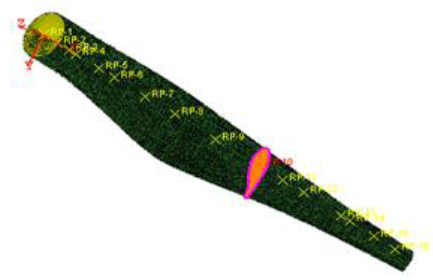
Figure 1.
Finite element model of 1.5MW wind turbine blade
According to the anisotropy of composite, the design criterion of the composite laminated plate, engineering practice, and experience, the laminate angles are from 30° to 50°, the 0°layer thickness ratio is from 10% to 40%, and three representative and regular stacking sequence are determined as the study scope, as shown in Table 1. In order to improve the overall resistance to tension and compression of the blade, a 0°or 90° unidirectional fiber cloth should be properly placed.
Table 1. Test scheme of blade’s ply parameters
| Laminate angle | 0°ply thickness ratio | Stacking sequence |
|---|---|---|
| 30° | 10% | ${{\left[ \pm x{}^\circ /{{\left( 0{}^\circ ,\pm x{}^\circ \right)}_{2}}/\pm x{}^\circ /{{\left( 0{}^\circ ,\pm x{}^\circ \right)}_{2}} \right]}_{\text{NT}}}$ |
| 45° | 30% | ${{\left[ {{\left( 0{}^\circ ,\pm x{}^\circ \right)}_{2}}/{{\left( \pm x{}^\circ \right)}_{2}}/{{\left( 0{}^\circ ,\pm x{}^\circ \right)}_{2}} \right]}_{\text{NT}}}$ |
| 50° | 40% | ${{\left[ \left( \pm x{}^\circ \right)/{{\left( 0{}^\circ ,\pm x{}^\circ \right)}_{4}}/\left( \pm x{}^\circ \right) \right]}_{\text{NT}}}$ |
3. First Order Design of Ply Parameters and Blade Static Performance based on Response Surface Method
3.1. The Design Flow of First-Order Response Surface
According to the test scheme, the test is designed based on the Taguchi design method in Minitab Software. In ABAQUS, the structural static strength and stiffness of each test scheme will be analysed. The data are processed by multivariate linear regression analysis, and the regression coefficient can be estimated. Thus, the first-order linear mapping relationship between the ply parameters and the single property parameter of the blade is obtained. The significance of the regression coefficient and regression equation is tested to determine whether the mathematical model is usable, and the influence degree of the factors on the response value is identified. The influence law of the ply parameters on the single performance of the blade will be explored. The design flow is shown in Figure 2.
Figure 2.
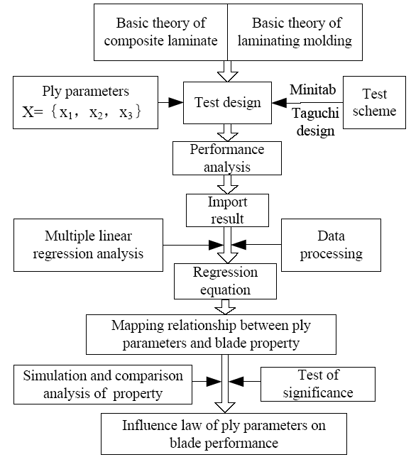
Figure 2.
Design flow of the response surface method
3.2. Response Surface Model and Significance Test
where $y$ is the response variable,${{x}_{i}}$ is the independent variable,$\varepsilon$ is the normal random error, ${{\beta }_{0}}$ is the regression intercept,${{\beta }_{i}}$ is regression coefficient, and $m$ is the number of independent variables.
After establishing the regression equation, it is necessary to test its significance, decide whether the mathematical model is usable, and determine the influence degree of the factors on the response value.
The significance test of the response surface equation is given as:
where $F$ is the confidence level of the response surface equation,$U$ is the square sum of regression,${{f}_{U}}$ is the degree of freedom,${{Q}_{E}}$ is the square sum of residual, and ${{f}_{QE}}$ is the corresponding degree of freedom.
Taking ${{F}_{\alpha }}$($\alpha =0.05$) as the reference standard of the significance test, if $F>{{F}_{\alpha }}\left( {{f}_{U}},{{f}_{QE}} \right)$, the response surface equation is meaningful. Otherwise, the response surface equation is not significant, which has little value when studying the laws between factors and variables[2].
The significance test of regression coefficient is the following:
If ${{F}_{i}}>{{F}_{\alpha }}\left( 1,\,{{f}_{QE}} \right)$, the factor ${{x}_{i}}$ in the response surface equation is significant, and it has greater influence on the static structural performance of the blade. Otherwise, this factor has no significant influence.
3.3. Establishing the First-Order Linear Mapping Relationship Between Ply Parameters and the Strength and Stiffness of the Blade
The test scheme of three factors and two levels is designed by means of the Taguchi design method in Minitab soft. The static strength and stiffness of the blade are analysed in ABAQUS. The test scheme and analysis results are shown in Table 2.
Table 2. Test scheme and analysis result
| Test No. | Layer angle | 0° ply thickness ratio | Stacking sequence | Tsai-Wu failure factor | Maximum displacement (mm) |
|---|---|---|---|---|---|
| 1 | 50° | 40% | 3 | 0.8028 | 877.6 |
| 2 | 50° | 40% | 1 | 0.8017 | 882.5 |
| 3 | 50° | 10% | 3 | 0.8940 | 991.1 |
| 4 | 50° | 10% | 1 | 0.8659 | 991.4 |
| 5 | 30° | 40% | 3 | 0.8016 | 873.6 |
| 6 | 30° | 40% | 1 | 0.8053 | 873.0 |
| 7 | 30° | 10% | 3 | 0.8872 | 987.8 |
| 8 | 30° | 10% | 1 | 0.9044 | 988.1 |
Figure 3.
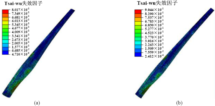
Figure 3.
(a) Tsai-Wu failure factor of test 2; (b) Tsai-Wu failure factor of test 8
Figure 4.
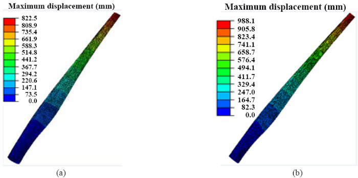
Figure 4.
(a) maximum displacement of test 2; (b) maximum displacement of test 8
According to the test results, each regression coefficient is estimated by means of the least squares method in regression analysis, and the first-order linear mapping relationship between ply parameters, the Tsai-Wu failure factor, and the maximum displacement is obtained respectively.
where ${{y}_{1}}$ is theTsai-Wu failure factor,${{y}_{2}}$ is the maximum displacement,${{x}_{1}}$ is the laminate angle,${{x}_{2}}$ is the 0° ply thickness ratio, and ${{y}_{3}}$ is the stacking sequence.
The significance test of the first order response surface equation between ply parameters and blade strength is given as follows.
Through calculation, $U=0.015$, ${{f}_{U}}=m=3$, ${{Q}_{E}}=0.00065$, and ${{f}_{QE}}=8-3-1=4$.
Then,
${{F}_{y1}}=\frac{U/{{f}_{U}}}{{{Q}_{E}}/{{f}_{QE}}}=\frac{0.015/3}{0.00065/4}=30.03>{{F}_{0.05}}\left( 3, 4 \right)=6.59$
This shows that the response surface equation of the Tsai-Wu failure factor is significant and usable.
Through calculation,
${{U}_{1}}=0.00015,\text{ }{{U}_{2}}=0.0145,\text{ }{{U}_{3}}=0.00001,\text{ }{{\overline{Q}}_{E}}=\frac{{{Q}_{E}}}{{{f}_{E}}}=0.00065/4=0.000162$
To $\alpha =0.05$, through look-up table[4]: ${{F}_{0.05}}\left( 1, 4 \right)=7.71$. Then,
${{F}_{1}}=\frac{0.00015}{0.000162}=0.90<{{F}_{0.05}}\left( 1, 4 \right)$
${{F}_{2}}=\frac{0.0145}{0.000162}=89.13>{{F}_{0.05}}\left( 1, 4 \right)$
${{F}_{3}}=\frac{0.00001}{0.000162}=0.05<{{F}_{0.05}}\left( 1, 4 \right)$
The 0°ply thickness ratio has significant influence on the static strength of the blade, and the influence of the laminate angle and stacking sequence is not significant.
In the same way, the significance test of the first order response surface equation between ply parameters and blade stiffness is given as follows.
Through calculation,$U=25558$, ${{f}_{U}}=m=3$, ${{Q}_{E}}=15.2$, and ${{f}_{QE}}=8-3-1=4$.
Then,
${{F}_{U}}=\frac{U/{{f}_{U}}}{{{Q}_{E}}/{{f}_{QE}}}=\frac{25558/3}{15.2/4}=2238.21>{{F}_{0.05}}\left( 3, 4 \right)=6.59$
This shows that the response surface equation of the maximum displacement is significant and usable.
Through calculation,
${{U}_{1}}=50.5,\text{ }{{U}_{2}}=25504.1,\text{ }{{U}_{3}}=3.0,\text{ }{{\overline{Q}}_{E}}=\frac{{{Q}_{E}}}{{{f}_{E}}}=15.2/4=3.8$
${{F}_{1}}=\frac{50.5}{3.8}=13.27>{{F}_{0.05}}\left( 1, 4 \right)$
${{F}_{2}}=\frac{25504.1}{3.8}=6700.59>{{F}_{0.05}}\left( 1, 4 \right)$
${{F}_{3}}=\frac{3.0}{3.8}=0.79<{{F}_{0.05}}\left( 1, 4 \right)$
The laminate angle and 0°layer thickness ratio has significant influence on the static stiffness of the blade, and the influence of stacking sequence is not significant.
4. Influence Analysis of Ply Parameters on the Blade Structure Property
4.1. The Macroscopic Influence of Ply Parameter on Static Strength of the Blade
It can be seen from Eq.(4) that when the stacking sequence is unchanged, with a gradual increase in the laminate angle and 0° ply thickness ratio, the Tsai-Wu failure factor of the blade decreases and the strength increases.
According to the experimental scheme and analysis results of Table 2, when the stacking sequence is 1, the 0°ply thickness ratio is 10% and 40%, respectively. The influence of the laminate angle on the static strength of the blade is shown in Figure 5. When the laminate angle increases from 30° to 50°, the Tsai-Wu failure factor decreases and the blade strength increases. The decreasing degree of the Tsai-Wu failure factor when the 0° ply thickness ratio is 10% is faster than that when the 0° layer thickness ratio is 40%.
Figure 5.
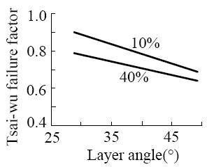
Figure 5.
Tsai-Wu failure factor with different laminate angles
When the stacking sequence is 1 and the laminate angle is 30° and 50° respectively, the influence of the 0° ply thickness ratio on the static strength of the blade is shown as in Figure 6. When the 0°ply thickness ratio increases from 10% to 40%, the Tsai-Wu failure factor decreases and the blade strength increases. The decreasing degree of the Tsai-Wu failure factor when the laminate angle is 30° is faster than that when the laminate angle is 50°.
Figure 6.
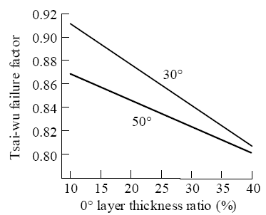
Figure 6.
Tsai-Wu failure factor with different 0° ply thickness ratios
When the laminate angle is 30°, the 0°ply thickness ratio is 10% and 40% respectively, and the influence of different stacking sequences on the static strength of the blade is shown in Figure 7. When the stacking sequence changes from 1 to 3, the Tsai-Wu failure factor decreases and the blade strength increases. The decreasing degree of the Tsai-Wu failure factor when the 0°ply thickness ratio is 10% is faster than that when the 0°layer thickness ratio is 40%.
Figure 7.
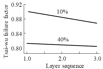
Figure 7.
Tsai-Wu failure factor with different stacking sequences
In summary, the greater the slope, the more obvious the influence degree. The influence degree of each factor on the static strength of wind turbine blade is different. Among them, the influence of the 0°ply thickness ratio is the greatest, followed by the laminate angle, and the stacking sequence has the least influence.
4.2. The Macroscopic Influence of Ply Parameter on Static Stiffness of the Blade
It can be seen from Equation(5) that when the stacking sequence remains the same, when the 0° ply thickness ratio gradually increases, the maximum displacement of the blade decreases and the strength increases. The stiffness of the blade decreases slightly as the laminate angle increases.
According to the experimental scheme and analysis results inTable 2, when the stacking sequence is 1, the 0°ply thickness ratio is 10% and 40% respectively, and the influence of the laminate angle on the static stiffness of the blade is shown in Figure 8. When the laminate angle increases from 30° to 50°, the maximum displacement increases and the blade stiffness decreases. The increasing degree of the maximum displacement when the 0°ply thickness ratio is 10% is slower than that when the 0°layer thickness ratio is 40%.
Figure 8.
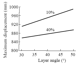
Figure 8.
Themaximum displacement with different laminate angles
When the stacking sequence is 1 and the laminate angle is 30° and 50° respectively, the influence of the 0° ply thickness ratio on the static stiffness of the blade is shown in Figure 9. When the 0°ply thickness ratio increases from 10% to 40%, the maximum displacement decreases and the blade stiffness increases. The decreasing degree of the maximum displacement when the laminate angle is 30° is faster than that when the laminate angle is 50°.
Figure 9.
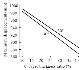
Figure 9.
Themaximum displacement with different 0°ply thickness ratios
When the laminate angle is 30°, the 0°ply thickness ratio is 10% and 40% respectively, and the influence of different stacking sequences on the static stiffness of the blade is shown in Figure 10. When the stacking sequence changes from 1 to 3, the maximum displacement is basically invariant, and there is almost no influence of the stacking sequence on the blade stiffness. The decreasing degree of the maximum displacement when the 0°ply thickness ratio is 10% is slightly faster than that when the 0°layer thickness ratio is 40%.
Figure 10.
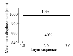
Figure 10.
The maximum displacement with different stacking sequences
Overall, the influence degree of each factor on the static stiffness of the blade is different. Among them, the influence of the 0°ply thickness ratio is the greatest, followed by the laminate angle, and the stacking sequence has the least influence.
5. Conclusions
Ply parameters have important influence on the property of wind turbine blades. From an engineering viewpoint, according to the design principle of the first-order response surface and Taguchi design method, the test scheme of ply parameters is designed, and the static strength and stiffness of the blade are simulated. The coefficient is estimated by the least squares method in regression analysis, and the first order linear mapping relationship between ply parameters, the Tsai-Wu failure factor, and the maximum displacement are established. The significance test is performed, and the influence of ply parameters on blade structure property is analysed. The results show that the influence of the laminate angle is not significant on blade strength and is significant on stiffness.The influence of the 0°ply thickness ratio on blade strength and stiffness are both significant, and the influence of the stacking sequence on blade strength and stiffness are not significant. The influence degree of each ply parameter on the static strength and stiffness of wind turbine blades is different. The influence of the 0°ply thickness ratio is the greatest, the laminate angle is the second greatest, and the stacking sequence has the least influence. The first regression model is suitable for this test, the method is feasible and effective, and the research has practical reference value.
Acknowledgements
The workis supported by the National Natural Science Foundation of China (No. 51665046), Foundation of Key Laboratory for Wind and Solar Power Energy Utilization Technology, Ministry of Education and Inner Mongolia Construction(No. 201606),and Caoyuan Elite Engineering of the Inner Mongolia Autonomous Region.
Reference
“Research Status and Development Trend on Large Scale Wind Turbine Blades, ”
DOI:10.3901/JME.2013.20.140
URL
[Cited within: 1]

Blade is one of key components of wind turbines. The wind rotor consisting of blades and hub is the energy capture mechanism which can transform the wind energy into mechanical energy. At the same time, blades are the force sources and bearing parts. Thus, blades play a key role for the safety of wind turbines. The industry development situation of modern large-scale wind turbines and its blades is analyzed. Then, a comprehensive summary is carried out including the aerodynamic shape and structural design, operation monitoring and control technology, the development trend and faced problems. The status and development trend of modern large scale wind turbine blades are grasped in general. It is specially pointed out that some fields will have further development such as the personalized airfoil design of anti-typhoon blades, low wind blades, bionic blades and low noise blades, design of novel wind turbine blade with sensing function of external environment load and structural state change. The formed blade design, manufacture and operation monitoring theory of wind turbines will be further improved and developed by service practice of large quantities of wind turbine in full life-cycle.
“Global Blending Optimization of Laminated Composites with Discrete Material Candidate Selection and Thickness Variation, ”
DOI:10.1007/s00158-015-1225-0
URL
[Cited within: 2]

A method capable of simultaneous topology and thickness optimization of laminated composites has previously been published by one of the authors. Mass constrained compliance minimization subject to...
“Influencing Analysis on Lamination Parameters to Static Structure Performance of Wind Turbine Blade, ”
“Coupling Effects Analysisof Laminating Parameterto Structural Propertiesof Wind Turbine Blade, ”
“Optimizing Design Research of Wind Turbine Blade based on Response Surface Methodology, ”
“Study on Optimization Design of Wind Turbine Blade with Composite Fiber Lamination Structure, ”
From the perspectives of engineering, taking the blade of certain 1.5 MW wind turbine as the research object and the most optimal structure performance as target, using the combining method of theoretical analysis, finite element analysis and structural optimization, applying hierarchical optimization strategy, the optimal mathematic model, objective function and constraint condition were established.The optimal lamination scheme of blade was obtained by optimizing lay-up angle, lay-up thickness and lay-up sequence, respectively.The structure analysis results indicate that the maximum principal stress and strain of the optimized blade are reduced obviously, respectively.The correctness and effectiveness of the optimization scheme and method are verified.
“Application of Response Surface Methodology in Experiment Design and Optimization, ”
“Optimization of Blade Setting Angles of a Counterrotating Type Horizontal Axis Tidal Turbine using Response Surface Methodology and Experimental Validation, ”
“Discrete Material and Thickness Optimization of Laminated Composite Structures Including Failure Criteria, ”
DOI:10.1007/s00158-017-1866-2
URL
[Cited within: 1]
This work extends the Discrete Material and Thickness Optimization approach to structural optimization problems where strength considerations in the form of failure criteria are taken into account...
“The Effect of the Beam Ply Parameters on Structure Performance of Wind Turbine Blade, ”
The effect of the beam ply parameters on structure performance of wind turbine blade has been studied. Based on the finite element method, a 1. 5 MW horizontal axis wind turbine blade was chosen as the research object. Beam ply was simulatedby using beam element in ANSYS software. Keeping the ply form of blade leading edge, trailing edge and the cap, a variety of research plansweregottenby changing the angle and order of beam ply or the proportion of layer number of different ply angle in whole layer number. Modal analysis was carried out on the blades of different solutions. The results show that the beam with plus or minus 45° ply will be able to bear shearing load better than other ply angle. Ply angle should be given priority to theuseof plus or minus 45°. The blade structure performance is best when plus or minus 45° ply accounts for around 58% of the whole ply. In order to reduce shear stress between the layers, 0° ply and 90° layer continuous plyshould be avoided.
“Mechanism and Optimization of Process Parameters Coupling for Composite Tape Winding, ”
DOI:10.13801/j.cnki.fhdxb.20150609.003
URL
[Cited within: 1]
The theoretical analysis of intimate contact and autohesion in molding process was carried out based on the research of composite winding process.The key process parameters affecting the quality of winding product, such as winding temperature, pressure and tension, were proposed.Based on Box-Behnken Design(BBD)theory of response surface methodology, the regression model of process parameters coupling on shear strength was established to optimize the interlaminar shear strength(ILSS).The reliability and effectiveness of regression model were verified through the test analysis such as residual, analysis of variance(ANVOA)and predicted versus actual.Furthermore, the optimal process parameters of winding process were obtained.Results illustrate that the winding products employing the optimum parameters bond in the highest strength with the interlaminar shear strength of22.9 MPa.
“A Novel Fiber Optimization Method based on Normal Distribution Function With Continuously Varying Fiber Path, ”
DOI:10.1016/j.compstruct.2016.10.064
URL
[Cited within: 1]
Tailoring fiber orientation has been a very interesting approach to improve the efficiency of composite structures. For the discrete angle selection approach, previous methods use formulations that requires many variables, increasing the computational cost, and they cannot guarantee total fiber convergence (which is the selection of only one candidate angle). This paper proposes a novel fiber orientation optimization method based on the optimized selection of discrete angles, commonly used to avoid the multiple local minima problem found in fiber orientation optimization methods that consider the fiber angle as the design variable. The proposed method uses the normal distribution function as the angle selection function, which requires only one variable to select the optimized angle among any number of discrete candidate angles. By adjusting a parameter in the normal distribution function, total fiber convergence can be achieved. In addition, a usual problem in fiber angle optimization methods is that because fibers can be arbitrarily oriented, structural problems may exist at the intersection of discontinuous fiber paths. Besides, composite manufacturing technologies, such as Advanced Fiber Placement (AFP), produce better results when fiber paths are continuous. These problems can be avoided by considering continuously varying fiber paths. In the proposed method, fiber continuity is also achieved by using a spatial filter, which improves the fiber path and avoids structural problems. Numerical examples are presented to illustrate the proposed method.
