


1. Introduction
Under the new normal state, the railway freight transportation management system, equipment technology, and change of market demand have strongly collided for many years, and the railway freight transportation and its technical development have faced severe challenges. Entering the “13th Five-Year”, China’s economy is still developing at an intermediate speed, and the overall social logistics are still growing at a high speed. The railway freight has its own unique advantages compared with highway, water transportation, and aviation.
With the development of urban rail transit, electric locomotives are being widely used in rail traffic. According to the statistics of the National Development and Reform Commission, the number of new electric locomotives from 2015 to 2017 maintained an average annual growth of about 15%. However, most of the locomotive failures are directly or indirectly related to bogies. Therefore, research on the reliability of locomotive bogie frames is particularly important [1-3].
The bogie is one of the most important components of EMU. It has three functions of driving, supporting, and guiding, which determine the safety and stability of train operation, as shown in Figure 1. The bogie frame of an electric locomotive is one of the most important parts of the bogie, and it is also the installation foundation of the other parts of the bogie. It not only bears the weight of parts, such as the car body, traction motor, and brake device, but also is influenced by the dynamic loads from different environments and different working conditions and bears the tasks of transmitting traction, braking force, lateral force, and vertical force [4].
Figure 1.
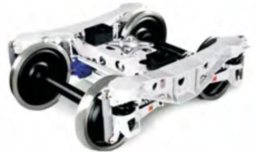
Figure 1.
Power locomotive bogie
The reliability of the bogie frame is directly related to the performance of the whole locomotive. Under the special conditions of heavy load, braking, and turning, the locomotives are subjected to repeated stress and heavy load impact of alternating stress, which is prone to fatigue deformation, fatigue crack, and failure [5]. Therefore, when designing the frame, it should not only ensure the interface size is reasonable and accurate, but also work safely and reliably in a given environment, and more importantly, it is necessary to meet the strength requirements for operation and ensure the stability and safety of the locomotive. In addition, in order to avoid accidents, it is necessary to ensure the reliability in the whole process of frame design, manufacture, actual operation, maintenance management, and so on. Among them, the research on reliability in the operation stage is the most important. In order to achieve the transformation from ex-post maintenance to pre-maintenance, we must evaluate the reliability of the architecture in operation [6].
At present, there are few studies on the reliability of locomotive frames, and their reliability is directly related to people’s travel safety and ride experience. Therefore, this paper is based on the 200km/h passenger electric locomotive bogie frame as the research object. Through three-dimensional solid modeling and analysis of the static strength and modal of the frame, it provides a reference for the evaluation of structural design and operation reliability and establishes a frame reliability evaluation model based on finite element analysis.
2. Frame Structure and Force of Locomotive Bogie
2.1. The Structure of Frame
In order to adapt to the operation of large axle loads and optimize the dynamic performance, the steering frame gives up three pieces of its frame structure, which consists of two symmetrical side beams, end beams, traction beams, and central beams.
The bogie frame of the 200km/h passenger locomotive adopts an approximate “H” shaped structure with transverse beams. It consists of two measuring beams with symmetrical sides and two beams with the same structure. Each beam has a certain number of partitions inside it, which is used to enhance the torsional stiffness of the frame. Main components include the spring suspension, shock absorber seat, traction rod base, anti-rolling torsion bar support, brake mounting base, and motor hanger. The total length of the frame is 4610mm, the total width is 2350mm, and the overall structure diagram of the frame is shown in Figure 2.
Figure 2.
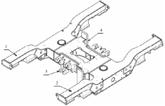
Figure 2.
Frame structure diagram of passenger 200km/h electric locomotive bogie
1. The right side beam; 2.The left side beam; 3.The first crossbeam; 4. The second crossbeam
The main structure of the frame is welded by a 16Mn steel plate, and the transverse beam is connected bya seamless steel tube to the side beam. 16Mn steel is a kind of low alloy and high strength structural steel. It has the characteristics of light quality, material saving, and excellent weldability. The performance parameters of 16Mn steel are shown in Table 1.
Table 1. Material properties of 16mn steel
| Material Properties | Value |
|---|---|
| Elastic Modulus (MPa) | 2.06e+05 |
| Poisson Ratio | 0.3 |
| Density (kg·m-3) | 7300 |
| Yield Limit (MPa) | 345 |
2.2. Analysis and Calculation of Structural Force
The vertical static load includes the gravity of the car body, axle, bogie, and passengers. The lateral load includes the wind force and centrifugal force of the car body. The longitudinal load has the traction force, friction force, and inertia force when braking. In addition, the dynamic load caused by vibration and shock is also included. The load and constraints are shown in Figure 3, and the technical parameters of the bogie frame are shown in Table 2.
Figure 3.
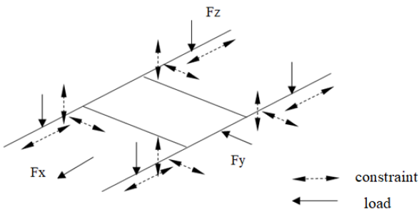
Figure 3.
A schematic diagram of the force of the bogie frame of a passenger locomotive
Table 2. Technical parameter table of bogie frame
| Parameter | Value |
|---|---|
| Gross rail load on Axle (t) | 21 |
| The weight of Bogie (t) | 26 |
| Weight with full Equipment(t) | 138 |
| Running Speed (km·h-1) | 200 |
| Traction Force(kN) | 285 |
The load analysis and parameters can be used tocalculate the load of the frame during the operations of the simulated locomotive. The results of the vertical, horizontal, and longitudinal loads are calculated, as shown in Table 3.
Table 3. Load calculation value
| Load type | Value |
|---|---|
| Vertical load (kN) | 211 |
| Lateral load(kN) | 116 |
| Longitudinal load(kN) | 142 |
3. Strength Calculation of Frame Finite Element
3.1. Architecture Modeling
In Pro-E, the three-dimensional solid modeling of the locomotive steering frame is modeled by the thin plate element based on the actual size, as shown in Figure 4.
Figure 4.
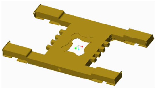
Figure 4.
Three-dimensional model of locomotive bogie frame
3.2. Static Strength Analysis of Frame
The three-dimensional model of the constructed frame is introduced into the finite element analysis software ANSYS Workbench 17.0, the material attributes are defined according to Table 1, and the static strength analysis is carried out.
For the frame finite element model, the two mesh generation methods, mapped grid and hexahedral element free grid, are used to divide the mesh, smooth the transition at the circular arc, and refine the mesh locally. The mesh results are shown in Figure 5.
Figure 5.
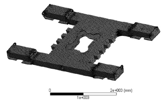
Figure 5.
Grid division of locomotive bogie frame
According to the actual conditions of the welded steel structure frame applied load and constraints, load the active role in the force on the surface of constraints imposed on the passive force at the start, perform calculations, and finally obtain the results of finite element analysis, including the equivalent stress diagram and total deformation effect, as shown in Figure 6.
Figure 6.
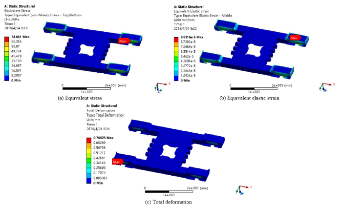
Figure 6.
The result diagram of finite element analysis
It can be known from Figure 6 that, firstly, the maximum stress is located in the inner side of the beam end and its value is 74.661MPa. This is less than the yield strength limit, which meets the requirements of reliability.Secondly, the equivalent plastic strain occurs at the end face of the beam, and the deformation is small. Thirdly, the maximum deformation of the frame is located outside the beam end, and the maximum deformation is 0.768mm.
The results show that the places where deformation and maximum stress occur easily are located at the ends of the two sides of the beam, the transition of the arc and the place where the weld is. These places also need to focus on the research of the reliability of the structure.
3.3. Modal Analysis of Frame
In the process of starting, driving, turning, and braking, the bogie frame will bump and vibrate. In most cases, vibration is harmful. It will affect the normal operation and use of locomotives. Therefore, to analyze the reliability of the structure, we must consider the effects and hazards caused by the vibration to confirm whether the internal structure of the bogie system has any problems such as failure, loosening, and wear, so as to provide reference for subsequent troubleshooting and maintenance[8-10].The material attributes are defined according to Table 1, as shown in Figure 7. The modal analysis of the frame is shown in Figure 8.
Figure 7.
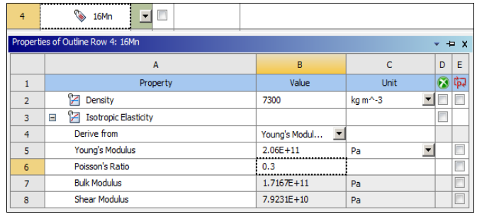
Figure 7.
Material attribute definition
Figure 8.
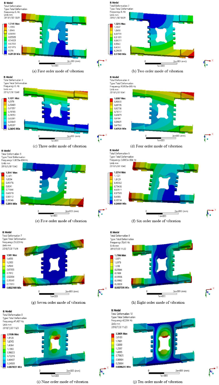
Figure 8.
Modal shape diagram of frame
From Figure 8, it is known that in the turbulence and vibration of the frame, the place where the vibration and deformation are easy to occur is located in the side beam and the end beam, and the closer to the edge, the greater the vibration. Therefore, by changing the mass distribution and weight reduction of the side beam, the purpose of avoiding resonance and reducing the impact is achieved, and the reliability of the frame can be enhanced.
According to the theory of modal analysis, the free modal of the frame finite element model is analysed, and the natural frequency and vibration mode of the former 10-steps mode of frame are computed. At the same time, the structural dynamic characteristics of the frame are determined and the weak of frame in the vibration is pointed out, which will provide reference for improving the design of dynamic characteristics, effectively preventing the phenomenon of resonance. Thus, it is significant for further dynamic analysis.
4. Reliability Model of Truck Frame
Based on the previous finite element analysis of the locomotive running stage, the actual force and vibration of the frame are simulated, providing the conditions for the reliability evaluation of the frame. The reliability assessment of specific parts is a personalized problem. It is necessary to consider the performance of the components itself as well as the use and maintenance performance of the specific working conditions [11-12].
In this paper, the reliability model of the locomotive steering frame is established. Combining the experience with the actual situation, the reliability of the frame is evaluated comprehensively to reduce the failure of the frame. The results provide a theoretical basis for the reliability test of locomotive bogie frames.
4.1. Influence Factors of Reliability of Locomotive Bogie Frame
In various stages of production, operation, and maintenance, the reliability will be influenced by the quality of the parts themselves, the existing technological level of the factory, the specific operation environment, and the maintenance[6,13-15].Refer to the relevant information and combine the actual situation to determine the influence factors of reliability, as shown in Figure 9.
Figure 9.
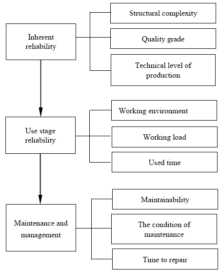
Figure 9.
Flow chart of influencing factors
4.2. Establishment of Structural Reliability Model
This paper is based on the theory of matter element, fuzzy evaluation, and analytic hierarchy process [5]. The reliability model of the framework is established from three aspects of the inherent reliability, the use stage, and the maintenance management stage. These three factors are chronological in the whole life cycle [16-18]. Only when the reliability of this stage is satisfied can the reliability of the next stage be considered.
First of all, the inherent reliability of the framework is a prerequisite for judging the overall reliability. Then, the reliability of the service stage is evaluated. This stage is very important. Finally, in the aspect of maintenance management, the reliability evaluation is carried out to ensure the safety and reliability of the locomotive frame.
If the three aspects meet the requirements of reliability, the model is established by the matter element theory, and then according to the weight distribution of AHP and the quantitative calculation of fuzzy evaluation, the overall scheme of the reliability of the selected frame is judged and improved [19]. Finally, determine whether the frame meets the requirements and obtain the size of the reliability.
Based on the above analysis, the overall evaluation model of locomotive frame reliability is obtained, as shown in Figure 10 below.
Figure 10.
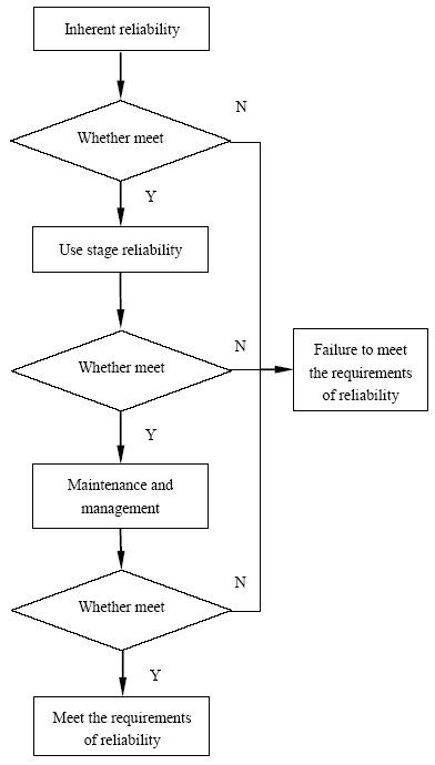
Figure 10.
Flow chart of structural reliability evaluation
(a) The reliability evaluation model of the frame is shown as follows:
(b) According to the matter element theory, a matter element model is set up as follows:
In the formula, $G$ is a classical domain, ${{r}_{1}}$, ${{r}_{2}}$, and ${{r}_{3}}$ are the evaluation index, and ${{v}_{1}}$, ${{v}_{2}}$, and ${{v}_{3}}$ are the actual values of the corresponding evaluation index.
(c) Determine the correlation function: the corresponding formula can be obtained from the definition of the middle distance in mathematics.
In this paper, the following function is used to solve the value of the correlation function:
In the formula, ${{r}_{i}}$ represents the value of each evaluation index of the framework to be evaluated, $i=1, 2,\cdots , n$; $\rho ({{r}_{i}},{{X}_{0i}})$ represents the distance between point ${{r}_{i}}$ and the valid interval ${{X}_{0i}}=\left( a, b \right)$.
(d) According to the analytic hierarchy process (AHP) and fuzzy evaluation, the evaluation coefficient of each evaluation index is determined. The following transformation is made to the judgment matrix A, the initial weight is calculated by formula (3), and formula (4) is normalized.
(e) A comprehensive evaluation model of the framework is established.
In the formula, n represents the number of reliability evaluation indexes, ${{W}_{i}}$ indicates the weight value of the evaluation index, and ${{k}_{i}}({{v}_{i}})$ indicates the value of the correlation function of the evaluation index. Only when $K(p)>0$ is satisfied is the reliability of the frame in line with the requirements, and the greater its value, the better the reliability.
5. Conclusions
(1) Through the static strength analysis and modal analysis of the frame, the maximum value of static stress appears at the junction of the side beam and the cross beam of the column. There is an obvious stress concentration in here. In addition, under the action of alternating stress, this place will suffer fatigue damage first. Thus, in order to avoid the occurrence of fatigue damage and improve the reliability of the frame, we need to improve the strength of the side beam and welding site and minimize the impact of emergency braking and heavy hauls.
(2) In view of the reliability problem where the locomotive bogie frame is in the actual operation stage caused by fatigue failure and shock vibration, the reliability analysis model of the frame based on finite element analysis is established in this paper. The model starts with the reliability of a single component and provides a reference for the analysis and research of the reliability of the individual parts.
(3) With the rapid development of rail transit, the reliability of locomotive bogie frames has become very important. In order to make the frame reliability model more accurately reflect the actual situation, we need to use finite element analysis software and field monitoring data to simulate the specific working conditions and perform specific assessments and optimization according to the reliability model.
(4) In order to ensure the reliability of the frame in the operation process, the allowable fatigue strength of the base material and the weld in the random variable of the structural reliability should be improved from the material selection of the frame and the control of the welding process, while the load on the two line air spring, lateral stop, and gear box is set up in the frame. The influence of them should be fully considered in order to improve the fatigue resistance of the frame.
Acknowledgements
This research was financially supported by the National Science Foundation of China (No.51565044).
Reference
“Connotation and Development of Mechanical Reliability-based Design, ”
“Review of Theory and Technology of Mechanical Reliability for Dynamic and Gradual Systems, ”
“Technology Status and Development of Fast Freight Car Bogies at Home and abroad, ”
“Passenger Transport 160 km/h Electric Locomotive Bogie Frame Reliability Analysis, ”
“Research on Dynamic Programming of the Series Manufacturing System Reliability Allocation, ”
“Component Reliability Criticality or Importance Measures for Systems with Degrading Components, ”
“Modal Analysis of Bogie Frame of Cross Seat Monorail Vehicle, ”
“Static Strength and Fatigue Strength Analysis and Modal Analysis of Bogie Frame of 30t axle Load Electric Locomotive, ”
“Optimization of High Speed AC Drives Co-Co Locomotive Steering Frame Optimization,
“Journal of Mechanical Equipment Reliability Assessment of the Development and Thinking of, ”
“Reliability Assessment of Multiple NC Machine Tools with Minimal Repair, ”
“Fuzzy Comprehensive Distribution and Prediction of Reliability and Maintainability of CNC Machine Tools, ” Jilin University,
“Reliability Analysis of Subway Vehicles based on the Data of Operational Failures, ”
DOI:10.1186/s13638-017-0996-y
URL

A large quantity of failure data for subway vehicles was collected from long-term field investigations and technical exchanged. These failure data has a guiding significance for preserving subway system. By preprocessing (screening, refining, and classification) the original data and statistical analysis, we establish some selected model, then we use A-D test to verify the degree of fitting in selected model so that we can determine the optimal failure distribution model, and then the reliability characteristic quantities could be calculated by the optimal failure distribution model. These reliability characteristic quantities can predict failure rate, failure number, etc. It can be used to assist proper maintenance scheduling to reduce the occurrence of accidents and significant to important practical guiding.
“Reliability Growth Design based on Reliability Allocation and Prediction for High Speed Precision Stamping Machine Tools, ”
“Fatigue Reliability Model of Bogie Frame Structure for High Speed Train, ”
DOI:10.3969/j.issn.1001-4632.2017.05.14
URL
[Cited within: 1]
In order to assess accurately the fatigue reliability of high-speed train bogie frame, the probability density function of the fatigue strength distribution under specified life was obtained through the multistage and small sample fatigue test data of the same material weld structure of bogie frame.With doubleparameter rain-flow counting method, the stress spectra were compiled according to the measured complex random stress-time history curve of frame structure.The corresponding symmetrical cyclic equivalent stress with constant amplitude was calculated according to the Miner criterion and fatigue damage equivalent principle.And the probability density function of the equivalent stress distribution under the service life of high-speed train was obtained by fitting the equivalent stress.Then, according to the obtained fatigue strength and equivalent stress distribution functions, the equivalent stress-fatigue strength reliability model of the bogie frame for high-speed train was established with the equivalent stress less than the fatigue strength as the fatigue failure criterion.Based on the data of welded structure fatigue tests and longterm tracking tests, the model was verified by taking the transverse beam joint on the bogie frame of a high speed train for the object.Results show that the model can be used to assess the fatigue reliability of the frame, and provide the evidence for the further optimization and whole life cycle management of welded frame structure.The reliability of the bogie frame structure for this type of high speed train reaches99.36% and thus has a higher safety factor under the service life of 12 million km total running mileage.
“Low Dynamic Performance and Connection Reliability of New Truck Radial Bogies, ”
“Research on Safety and Reliability Analysis and Evaluation Method of High-Speed Train System, ”
“Reliability Assessment of Manufacturing Processes, ”
