


1. Introduction
The breech mechanism is the key subsystem of large-caliber guns, and it serves to close the breech, fire the ammunition, and extract the cartridge case [1]. Usually, the breech mechanism of large-caliber guns is semiautomatic vertical sliding-wedge type. It consists of the breechblock assembly, semiautomatic device, firing device, safety device, shell stop device, and extractor assembly. The whole number of essential parts of the breech mechanism is more than one hundred [1-2]. The heaviest part is the breechblock, whose weight is more than 76 kg. The lightest part weighs less than 0.01 kg. A tremendous impulse force acts on the parts of the breech mechanism in a short time, which results in significant wear, fatigue, and collisions. Statistical data show that the fault rate of the breech mechanism is more than 50% for the firepower system [3-4]. In order to improve the gun’s operational reliability, the breech mechanism is taken as a research object to carry out reliability enhancement tests and motivate the underlying weaknesses rapidly in this paper. Micro-texture anti-friction design and solid lubrication technology were developed to improve the specific weakness and realize reliability growth.
Traditional reliability tests and evaluation technologies require long periods and mass money [5-6]. The reliability enhancement test is a new kind of method to inspire the part invalidation of the breech mechanism. It provides a more rigorous test condition than the natural service condition by increasing test stress. Reliability enhancement tests can accelerate the part invalidation process to reveal reliability weakness segments in a short time [5, 7]. Appropriate improvement and optimization technologies can be adopted to improve the reliability weakness segments. Presently, research on reliability enhancement tests of electronic products has acquired remarkable academic and applied achievements [8]. However, research on reliability enhancement tests of mechanical products is limited [9]. In particular, there are still no systematic and profound research findings regarding reliability enhance tests of large-caliber guns, due to the lack of corresponding reliability enhancement test theory, technology, and equipment. This paper takes the breech mechanism of a large-caliber gun as a research object to generalize feasible reliability enhancement methods and explore effective reliability growth technologies.
2. Establishment of Reliability Enhancement Test Bed for Breech Mechanism
The enhancement test stress of the breech mechanism depends on the counter-recoil breechblock-opening velocity. Increasing the charge in firing and raising the striking velocity from the muzzle modify the counter-recoil breechblock-opening velocity and dynamic parameters of the breech mechanism by small amplitudes [10]. The reliability enhancement test bed is designed and established to carry out reliability enhancement tests of the breech mechanism. Compared with service firing, reliability enhancement tests based on test bed reduce dangers and increase the efficiency-cost ratio.
The functions of the test bed are to finish the breechblock opening and close tests for the breech mechanism. Specific functions include:
(1) It is applicable for impacting breechblock-opening guns, and it can finish automatic breechblock-opening, automatic breechblock-closing, and continuous breechblock opening and closing.
(2) It can simulate the breechblock opening and closing processes of live firing and provide basis for reliability enhancement tests and accelerated life tests of the breech mechanism.
(3) The impact parameters are adjustable to the normal working condition and different enhancement test conditions.
(4) It has a crawl mode and series mode. The crawl mode is used to control the manual breechblock opening and closing processes. The series mode is used to control the automatic continuous breechblock opening and closing processes.
2.1. Technical Indexes
According to the dynamic parameters of live firing tests and the periods of breechblock opening and closing, the test bed technical indexes of reliability enhancement tests are as follows:
(1) The drive force is more than 2427.4N; the drive velocity is more than 0.85m/s.
(2) The test frequency of automatic breechblock opening and closing is 3-5 degrees per minute.
(3) The no-failure continuous breechblock opening and closing number of the reliability enhancement test bed is more than 500.
(4) The power of the automatic pushing bar is 24V and direct current, the maximal pushing force is 100kg, the pushing velocity is 10mm/s, and the maximum extension length is 90mm.
(5) The weight of the single mass block of the breechblock-opening mechanism is 15.3kg.
2.2. Tables Structural Composition
The reliability enhancement test bed of the breech mechanism is mechanical, electrical, hydraulic integrated test equipment, which consists of body, breech mechanism, supporting and fixing device of breech, power output device, breechblock-opening device, breechblock-closing device, and control and test device. The breech mechanism roots in a kind of service large-caliber gun. The hydraulic system adopts the valves produced by Beijing Hade Corporation. The control system adopts the programmable logic controller of EC10-1410BRA type. The displacement measurement of the breechblock adopts a potentiometer sensor of PT1DC type. Its measuring range is 50 inches. Its sensitivity is 3.9370mV/mm. The dynamic characteristic measuring of the load sliding table adopts laser sensors of ZLDS100 type. Its measuring range is 1510mm. Its sampling frequency is 9.4kHz. Its wave length is 660nm. When the reliability enhancement test bed of the breech mechanism begins to work, the power output device provides breechblock-opening power, the breechblock-opening plate crashes the crank in its moving process towards breech-end, and the percussion force drives the breechblock moving downward. The breechblock-closing process is completed by the breechblock-closing device.
3. Reliability Enhancement Test Bed for Breech Mechanism
Based on the reliability enhancement test principle and the reliability enhancement test bed of the breech mechanism, the working extreme stress can be analyzed and the intensified test stress can be determined.
Figure 1.
Figure 1.
Reliability enhancement test bed of breech mechanism
3.1. Extreme Working Stress Measurement of Test Bed
3.1.1. Driving Mass
According to the masses of the breechblock-opening plate, support arm, load sliding table, and mass block on the reliability enhancement test bed, the maximum value of the driving mass is 149kg and the minimum value of the driving mass is 72.5kg. The intermediate values include four steps, which are determined by the number of driving masses.
3.1.2. Pressure of Overflow Valve
When there is no load on the breechblock-opening device, adjust the pressure control knob of the overflow valve and measure the pressure range of the hydraulic pressure. The result of the pressure range of the overflow valve is 0 ~ 10Mpa.
3.1.3. Driving Velocity
Figure 2.
Figure 2.
Displacement curve of load sliding table
Figure 3.
Figure 3.
Velocity curve of load sliding table
Figure 2 shows the displacement curves of three shuttle processes of the load sliding table. Because there is a given distance between the laser sensor and the load sliding table, the initial displacement is not zero. The actual displacement is 0.470m, which is consistent with the breechblock-opening range. Figure 3 shows that there are obvious waves on the velocity curve. Especially when the load sliding table touches the terminal limit switch, the electromagnetic valve breaks off, the hydraulic system lies off, the velocity of the load sliding table drops suddenly, and there are obvious peak impulses. However, there are minor waves in the breechblock-opening process and breechblock-closing process. The equalization of the breechblock-opening velocity is 0.38m/s.
Adjust the knob of the flow regulating valve and measure the velocity curves of the load sliding table (Figure 4 and Figure 5). In Figure 4, the velocity equalization of the load sliding table is 0.49m/s. Then, adjust the pressure of the overflow valve to 5MPa and measure the velocity of the load sliding table when the hatch of the flow regulating valve is maximized. In Figure 5, the velocity equalization of the load sliding table is 0.892m/s. The above measurement results show that when the hydraulic pressures are different and the hatches are same, the driving velocities of the enhancement test bed are also different, and the velocity control of the flow regulating valve is influenced by the pressure of the overflow valve. By adjusting the hydraulic pressure continuously, when the pressure of overflow valve is 10MPa and the knob of the flow regulating valve is maximized, the maximum driving velocity of breechblock-opening is 1.269m/s, which illustrates that the maximum current velocity of the hydraulic system decreases because of the loads and other middle floating resistances. Considering the above influencing factors, the driving velocity range of the enhancement test bed is 0 ~ 1.269m/s.
Figure 4.
Figure 4.
Velocity curve of load sliding table when P = 2.5MPa
Figure 5.
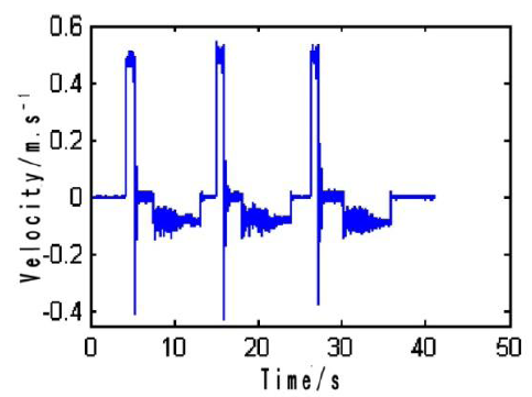
Figure 5.
Velocity curve of load sliding table when P = 5.0MPa
3.1.4. Driving Distance
The driving distance only influences the acceleration process of the load sliding table from stillness to steady speed and has no effects on the breechblock-opening process. Therefore, the distance between the front edge of the breechblock plate and the curved surface of the crank should be guaranteed, and the velocity of the load sliding table should be stable. The distance is determined by the position of the rear limit switch, which is fixed at 0.295m.
3.2. Determination of Enhancement Test Stress
According to the measurement results of the reliability enhancement test, take the breechblock-opening indexes (the driving mass is 72.5kg, the pressure of the overflow valve is 3MPa, and the driving velocity is 0.49m/s) as primary test parameters, increase them in the breechblock-opening and breechblock-closing tests, and measure the displacement and the velocity of the breechblock. They are shown in Figure 6.
Figure 6.
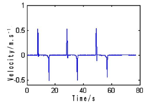
Figure 6.
Breechblock velocity under primary parameters
Figure 7 shows that the increase in the driving mass has little influence on the decrease in the breechblock velocity, there are no obvious difference among different velocity peaks, and the maximum velocities of the two different driving masses are 0.525m/s and 0.556m/s. Figure 8 and Figure 9 show that with an increase in the pressure of the overflow valve and the driving velocity, the breechblock velocity decreases obviously. If the breechblock velocity increases, the wear-out-failure parts will increase the relative sliding velocities and working stresses and the fatigue-out-failure parts will increase the dynamic loads. For example, the wear extent of the cocking cam and the impact of the closing spring will increase, which are also the stress enhancement processes. Therefore, for reliability enhancement tests of the breech mechanism, the enhancement test stresses are the driving mass, the driving velocity, and the pressure of the overflow valve.
The setting pressure of the overflow valve is not directly acting on the piston rod, which directly influences the flow of the hydraulic cylinder and the driving velocity of the piston rod. In the subsequent reliability enhancement test process, if the enhancement effects of the overflow valve are not considered and the extreme pressure is set as 10MPa directly, the test working conditions are consistent with the actual working conditions.
Figure 7.
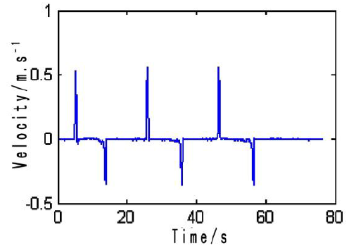
Figure 7.
Breechblock velocity when M = 118.4kg
Figure 8.
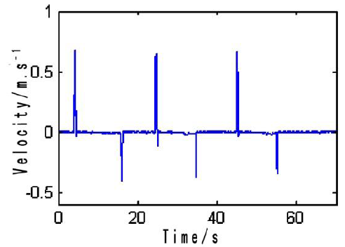
Figure 8.
Breechblock velocity when P = 5MPa
Figure 9.
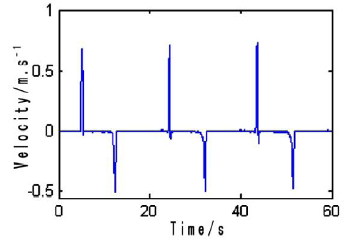
Figure 9.
Breechblock velocity when V = 0.73m/s
3.3. Determination of Enhancement Stress Level
The normal stress levels can be determined by the simulated working conditions. The driving mass is 72.5kg, and the driving velocity is 1.124m/s. If the pressure of the overflow valve is set as 10MPa, increasing the mass number and adjusting the hatch area of the flow regulating valve will enlarge the stress levels of the reliability enhancement test. In the extreme range of the working stress, select the enhancement test stress levels as shown in Table 1. The driving mass is determined by the mass number. The driving velocity is determined by the velocity of the load sliding table under different hatch areas of the flow regulating valve.
Table 1. Stress level of enhancement test
| Test stress | Normal stress level | Enhancement stress level | |||
|---|---|---|---|---|---|
| 0 | 1 | 2 | 3 | 4 | |
| The driving mass (kg) | 72.5 | 87.8 | 103.1 | 118.4 | 133.7 |
| The driving velocity (m/s) | 1.124 | 1.183 | 1.21 | 1.252 | 1.269 |
4. Reliability Enhancement Test of Breech Mechanism
Reliability enhancement tests under different stress levels can be carried out based on the enhancement test bed. Considering the number limitation of test objects, the usual stress load operation of equivalent step is adopted. Firstly, the step stress test of driving mass is accomplished. Then, the step stress test of driving velocity is accomplished. Finally, the comprehensive stress test is accomplished. Based on limited test conditions, most possible potential defects can be excited.
4.1. Section Design of Enhancement Test under Single Stress Level
When the driving force and the driving velocity are given, the modification of the driving mass will influence the momentum between the breechblock-opening plate and crank directly. With an increase in the driving mass, the momentum of breechblock-opening will also increase. The impulse when the breechblock-opening plate impacts the crank will increase immediately. The dynamic load and the working stress will also increase to excite latent defects. When the other stress levels are constant, only change the driving mass to perform the breechblock opening and closing tests. The continuous number of enhancement tests is 50. The corresponding test section is shown in Figure 10, where “a” denotes the continuous test process of breechblock opening and closing and “b” denotes the motion detection of the test mechanism.
Figure 10.
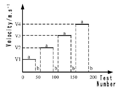
Figure 10.
Breechblock velocity when P = 5MPa
The driving velocity can also influence the momentum between the breechblock-opening plate and the crank. With an increase in the driving velocity, the breechblock-opening momentum will also increase. When the other stress levels are normal, only change the stress level of the driving velocity to proceed with the breechblock opening and closing test [11]. The continuous number of enhancement tests is also 50. The corresponding test section is shown in Figure 11.
Figure 11.
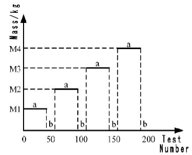
Figure 11.
Breechblock velocity when V = 0.73m/s
4.2. Section Design of Enhancement Test under Comprehensive Stress Levels
In order to strengthen the test effects, reliability enhancement tests under comprehensive stress levels are carried out based on the stress level ranges in Table 1. Change two stress levels of the enhancement test to accomplish an all-array test of two elements and four levels. The corresponding test section is shown in Figure 12 [12-13]. The test number of every stress level is 50. Detect the mechanism action after each test. If there is no fault, continue the enhancement test according to the test section. If there is still no fault after the tests of all stress levels, continue the enhancement test under the maximum stress level M4-V4.
Figure 12.
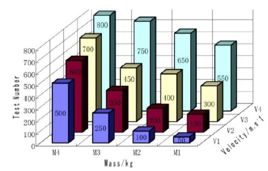
Figure 12.
Enhancement test section under comprehensive stresses
4.3. Implementation of Reliability Enhancement Test
According to the test sections of single stress level and comprehensive stress levels, carry out the reliability enhancement test of the breech mechanism and count the test number using a magnetic counter [14]. Figure 13 shows that the breechblock-opening plate slides the inclined plane of the crank in the recovery process of the load sliding table after opening the breechblock. Figure 14 shows the magnetic counter and the counting process. The test numbers under different stress levels are shown in Table 2.
Figure 13.
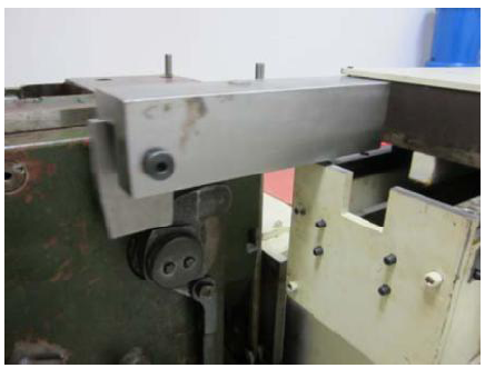
Figure 13.
Process of reliability enhancement test
Figure 14.
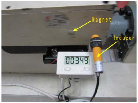
Figure 14.
Magnetic counter and the counting process
Table 2. Results of the reliability enhancement test for breech mechanism
| Driving velocity | Driving mass | ||||
|---|---|---|---|---|---|
| M0 | M1 | M2 | M3 | M4 | |
| V0 | - | 50 | 50 | 50 | 50 |
| V1 | 50 | 50 | 50 | 50 | 27 |
| V2 | 50 | 50 | 50 | 50 | |
| V3 | 50 | 50 | 50 | 50 | |
| V4 | 50 | ||||
The comprehensive stress test is carried out after the single stress test. The fault of being unable to extract the cartridge case occurs in the 27th comprehensive test of the M4-V1 stress level. If there is the same fault in the service firing process, the gun will be unable to load the next projectile and cartridge case. By means of the reliability enhancement test of the breech mechanism, the potential faults can be excited. According to the flow of the reliability enhancement test, the corresponding fault reasons and the potential flaws should be analyzed in order to provide theoretical basis for flaw elimination and reliability improvement.Fault mode and effect analysis is carried out according to the above fault phenomenon. There are two kinds of fault modes that lead to fault occurrence, one is the mechanical wear between the shaft arm of the shell stop and the arm of cocking shaft, while the other is the screw overhang of the shell stop. By means of fault detection, the actual fault reason is the mechanical wear between the shaft arm of the shell stop and the arm of cocking shaft. Decompose the shell stop device and check the shaft arm of the shell stop and the arm of the cocking shaft. There are obvious scratches along the sliding direction on the surfaces. The imaginable line squares in Figure 15 and Figure 16 show that there is superficial organization exfoliation on the shaft arm of the shell stop, which illustrates that the wear consequence of the shaft arm of the shell stop is more severe than that of the cocking arm of the shell stop. In order to judge the wear extent exactly, an electronic analytical balance type of EX324ZH is used to weigh the worn part. Compare the worn part and the new part, and average three sequential measurement results. The average results are shown in Table 3.
Figure 15.
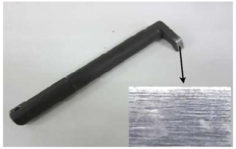
Figure 15.
Worn surface of the shaft arm of the shell stop
Table 3 shows that the quality of the tow worn parts is less than that of the new parts. Therefore, the wear of the shaft arm of the shell stop and the arm of the cocking shaft results in the cartridge clamping stagnation. Replace new parts of the shaft arm of the shell stop and the arm of the cocking shaft to test the breechblock opening and closing functions. The test bed of the breech mechanism recovers normal actions, which certifies the fault analysis conclusions.
Figure 16.
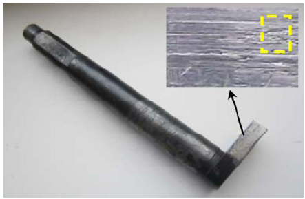
Figure 16.
Worn surface of the arm of the cocking shaft
Table 3. Comparison between worn part and new part
| Item | Shaft arm of shell stop | Arm of cocking shaft | ||
|---|---|---|---|---|
| Worn part | New part | Worn part | New part | |
| Weight | 213.01323 | 215.66747 | 228.03660 | 229.73337 |
5. Research on Wear Failure Mechanics based on Microscopic Analysis
The existing literature and research findings on part wear of the breech mechanism concentrate on fault analysis caused by wear or wear life evaluation. Wear failure mechanics are not analyzed in detail. This paper analyzes the part’s wear process from surface topography, microstructure variation, etc.
Transmit the solid models of the breech mechanism into the finite element software to establish the finite element models and analyze the mutual dynamical process of the shaft arm of the shell stop and the arm of the cocking shaft. The simulation results include the equivalent stress distribution at different times. Figure 17 is the stress distribution when t = 0.0023s. Select ten nodes at the same interval along the arm surface in the sliding direction. Based on the finite element analysis, the maximum equivalent stress distribution curve of all nodes on the part surface can be obtained and are shown in Figure 18.
Figure 17.
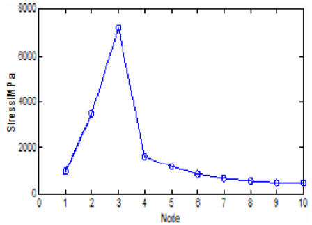
Figure 17.
Stress cloud figure when t = 0.0023s
Figure 18.
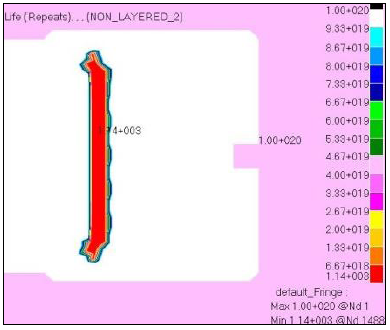
Figure 18.
Maximum stress distribution curve on part surface
Figure 18 shows that the maximum equivalent stress of node 1 to node 5 is greater than the material ultimate strength 835 MPa. The stresses of node 2 and node 3 are greater than this ultimate strength, which illustrates that there is severe flake and plastic deformation in this area. The maximum equivalent stress of node 6 is less than the ultimate strength but greater than the yield strength 685MPa, which illustrates that there is plastic deformation around the node. The maximum equivalent stress of node 7 to node 10 is less than the yield strength. The variation process is gentle.
The material of the shaft arm of the shell stop is PCrMo, whose partial element composition is shown in Table 4. To analyze and compare the variation and difference of the surface pattern and microstructure before and after wear of the shaft arm of the shell stop, sample from the worn area and unworn area.
Table 4. Element composition of PcrMo
| Element | C | Si | Mn | Cr | Ni |
|---|---|---|---|---|---|
| Percentage composition | 0.32~0.40 | 0.17~0.37 | 0.25~0.5 | 0.9~1.3 | ≤0.5 |
| Element | Mo | Cu | P | S | |
| Percentage composition | 0.2~0.3 | ≤0.2 | ≤0.025 | ≤0.025 |
The sample surface hardness of the worn area and unworn area is shown in Table 5. It shows that the hardness of the unworn area has narrower variation range and better compatibility. However, the hardness of the worn area increases obviously. Combined with the above stress analysis, there is plastic deformation and hardening of the surface metal layer caused by collision and friction between parts.
Table 5. Sample surface hardness of worn area and unworn area
| Test surface | 1 | 2 | 3 | 4 |
|---|---|---|---|---|
| Worn area | 563.1 | 535.7 | 558.3 | 527.6 |
| Unworn area | 458.2 | 458.7 | 452.3 | 463.1 |
| Test surface | 5 | 6 | 7 | |
| Worn area | 559.9 | 565.1 | 559.5 | |
| Unworn area | 457.1 | 461.9 | 461.9 |
Figure 19 presents the SEM micrographs, which show there are flakes, pan furrows, and holes. The pan furrows are along the relative movement direction. The massive flakes form notches. The abrasive dusts embed into the worn surface. Therefore, the initial wear process is impact sliding coupling wear, and the later wear process is abrasive particle wear [15-16]. Abrasive particle wear usually results in severe surface damage.
Figure 19.
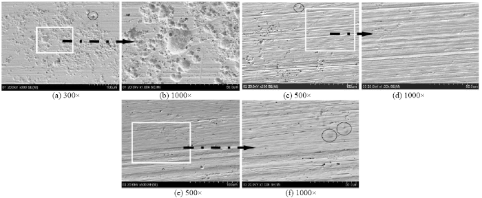
Figure 19.
SEM Micrograph
Based on the surface pattern analysis, composition analysis, cross section organization analysis, and hardness analysis, the following conclusions can be generalized:
(1) There is obvious plastic deformation on the surface metal layer caused by collision and friction, which results in the hardness increase of the surface and cross section.
(2) The initial wear process is impact sliding coupling wear. The later wear process is abrasive particle wear.
6. Conclusions
In order to improve the reliability of the breech mechanism for large-caliber guns, a reliability enhancement test bed is designed and established according to the actual equipment. Test stress and stress levels are determined based on the extreme measurement results and enhancement effectiveness. The cross sections of single stress enhancement tests and comprehensive stress enhancement tests are designed. By means of the reliability enhancement test, the fault of impossible extracting is excited. Microscopic observations and analysis illustrate the wear failure mechanics. Impact sliding coupling wear and abrasive particle wear are the prime failure reasons of the shaft arm of the shell stop and the arm of the cocking shaft.
Reference
“Kinematic and Dynamic Simulation of Breech Mechanism based on Virtual Prototype, ”

Based on the CAD software Pro/E and dynamic simulation software ADAMS, the Virtual Prototype of a new kind of breech mechanism of mortar-howitzer gun is established. In order to recur the working process of breech mechanism, the models of driving force acting on recoil part in counterrecoil process and collision force working process of breech and spring force are founded. The kinematic characteristics of breech mechanism and the collision force between breech-opening plate and crank, the collision force between roller of closing lever and supporting sleeve, the spring force of breech-closing and the spring force of pressing-bolt are simulated kinematically. The comparison between simulation consequences and actual working process of breech mechanism validates the credibility of the Virtual Prototype.
“Dynamic Characteristics of Extractor System in Artillery Vertical Wedge Breechblock, ”
DOI:10.11883/1001-1455(2017)02-0221-08
URL
[Cited within: 1]

Aimed at the faults such as cartridge jamming and component dynamic fracture in the extractor system of an artillery vertical wedge breechblock, this paper was focused on transforming the extracting fault analysis to the quantitative study of the system dynamic characteristics based on the nonlinear dynamics theory.The working mechanism of the extractor system was analyzed firstly, and then a continuous contact dynamics model was established for deriving out the motion law of any components and the impact loads quantificationally during the extraction process.Moreover, the elastic wave model of the lever-type extractor was established, which can both describe the dynamic stress distribution and achieve the influences of the mechanical parameters of the extractor by the quantitative form.The numerical calculation of those theoretical models and the simulations of the virtual prototype were both conducted on the ideal extracting condition.The comparison results of the same group show that the quantitative analysis dynamic models are reasonable and effective, which provides a theoretical basis for the solution of the extracting fault and the dynamics optimization of the extractor system.
“Discussion on Reliability Enhancement Test Scheme of Gun Mechanical Systems, ”
“Research on Reliability Enhancement Testing Technology of Breech Firing Mechanism, ”
“Study on Reliability Enhancement Testing for InSb Focal Plane Array Detector, ”
in
DOI:10.1117/12.900272
URL
[Cited within: 2]
InSb focal plane array (FPA) detectors which are important components of infrared systems have great influence on systems' reliability and development. Few researches have been focused on this field in recent years. Therefore, it is rather essential to carry out reliability test. In the paper, reliability enhancement testing has been carried out on 128 128 elements InSb FPA detectors to discuss the influence of temperature stresses and vibration stresses on structure and performance. Working boundary conditions of InSb FPA detectors were obtained. Aiming at the failure the corresponding improvements were adopted, and reliability of detector was enhanced greatly.
“Comprehension and Implementation of Reliability Enhancement Testing for Ammunition, ”
in
DOI:10.1109/ISME.2010.13
URL
[Cited within: 1]
How to improve and raise the reliability of high-new-technique ammunition and ammunition component has already become a problem not allowing of being neglected. The weak part of ammunition and the main environment sensitivity stress which influences its storage reliability have been analyzed in this paper. According to the theory of reliability enhancement testing and the technique characteristics of a certain ammunition component, a scheme of reliability enhancement testing for the ammunition component was designed. Reliability enhancement testing for the ammunition component was carried out by the scheme. The test results indicate that the scheme has a better effect on making sure of operating limit and destruct limit and exciting the latent defects of the ammunition component. The research results offered a method to develop reliability enhancement testing for the similar component of high-new-technique ammunition and a new technique approach to improve and raise the reliability of high-new-technique ammunition and ammunition component.
“Mechanisms of Self-Lubrication in Patterned TiN Coatings Containing Solid Lubricant Microreservoirs, ”
DOI:10.1016/j.surfcoat.2010.01.012
URL
[Cited within: 1]
The tribological mechanisms of friction and lubrication have been investigated in TiN coatings patterned to contain microscopic reservoirs for solid lubricant entrapment. Photo-lithography was used to fabricate three sets of samples on silicon wafers, varying the reservoir size (4 and 9 μm) and spacing (11 and 25 μm), which resulted in samples with a nominal reservoir area of either 2 or 10%. Pin-on-disk tests were run using lubricants of graphite and indium and counterfaces of alumina and steel (440C). In most cases, the samples with the 9 μm holes spaced 25 μm apart gave the lowest friction coefficients and longest wear life. Analysis of the wear tracks by SEM/EDS methods showed carbon to be present in the holes of the graphite/steel counterface samples, but TiO 2 was found in the holes of the graphite/alumina counterface samples. For the indium/steel counterface samples indium was detected within the microreservoirs, but iron was also found, transferred from the ball. These experiments highlight a variety of tribological mechanisms that can operate in microreservoir-patterned coatings.
“The Application of Accelerated Testing Methods and Theory HALT, HASS and HASA, ”
“Impact Fretting Wear Behaviour of Alloy 690 Tubes in Dry and Deionized Water Conditions, ”
DOI:10.1007/s10033-017-0147-8
URL
[Cited within: 1]
The impact fretting wear has largely occurred at nuclear power device induced by the flow-induced vibration, and it will take potential hazards to the service of the equipment.However, the present study focuses on the tangential fretting wear of alloy 690 tubes.Research on impact fretting wear of alloy 690 tubes is limited and the related research is imminent.Therefore, impact fretting wear behavior of alloy 690 tubes against 304 stainless steels is investigated.Deionized water is used to simulate the flow environment of the equipment, and the dry environment is used for comparison.Varied analytical techniques are employed to characterize the wear and tribochemical behavior during impact fretting wear.Characterization results indicate that cracks occur at high impact load in both water and dry equipment;however, the water as a medium can significantly delay the cracking time.The crack propagation behavior shows a jagged shape in the water, but crack extended disorderly in dry equipment because the water changed the stress distribution and retarded the friction heat during the wear process.The SEM and XPS analysis shows that the main failure mechanisms of the tube under impact fretting are fatigue wear and friction oxidation.The effect of medium(water) on fretting wear is revealed, which plays a potential and promising role in the service of nuclear power device and other flow equipments.
“Research on the Application of Reliability Enhancement Test Technology in Servo System, ”
The servo system is one of the core components of industrial robots. How to quickly shorten the development cycle and improve the overall reliability of the servo system is an urgent problem to be solved in the development process of industrial robots, and the reliability enhancement test technology can play an important promoting role in this field. Combining with the characteristics of servo system, a reliability enhancement test method for servo system based on complex system is put forward, and the implementation flow of reliability enhancement test of servo system is given. Besides, by selecting a typical industrial robot servo system to carry out the reliability enhancement test, the weak links and stress limit of the servo system are found out.The research shows that the reliability enhancement test technology can quickly and efficiently expose the weak links of the servo system, and it has certain reference value for improving the reliability of the servo system.
“The Application of Reliability Enhancement Testing Technology in the Development of Aerospace Equipment, ”
With the development of aerospace technology, higher reliability of equipment is demanded. But nowadays, most of the reliability testing for the space equipment is still using traditional methods which are so difficult to find possible faults of the equipment regarding its higher reliability and longer life. The reliability enhancement testing is a new type of reliability testing method, can improve the aerospace equipment inherent reliability with higher efficiency and lower costs and has already been applied to the national launch vehicle.
“Dynamic Corrosion Properties of Impact-Fretting Wear in High-Temperature Pure Water, ”
DOI:10.1016/j.wear.2014.11.029
URL
[Cited within: 1]
61The synergistic effects of corrosion and wear are significant in impact-fretting.61We proposed a wear model for impact-fretting in high-temperature pure water.61Dynamic corrosion agreed with the parabolic law of oxidation of metals.61The activation energy of dynamic corrosion was about 10kJ/mol in water.61Cr oxide on the steel surface acted as a protective film in pure water at 130°C.
“Heat Transfer Enhancement with Mixing Vane Spacers using the Field Synergy Principle, ”
DOI:10.3901/CJME.2016.0621.076
URL
[Cited within: 1]
The single-phase heat transfer characteristics in a PWR fuel assembly are important. Many investigations attempt to obtain the heat transfer characteristics by studying the flow features in a 5 5 rod bundle with a spacer grid. The field synergy principle is used to discuss the mechanism of heat transfer enhancement using mixing vanes according to computational fluid dynamics results, including a spacer grid without mixing vanes, one with a split mixing vane, and one with a separate mixing vane. The results show that the field synergy principle is feasible to explain the mechanism of heat transfer enhancement in a fuel assembly. The enhancement in subchannels is more effective than on the rod's surface. If the pressure loss is ignored, the performance of the split mixing vane is superior to the separate mixing vane based on the enhanced heat transfer. Increasing the blending angle of the split mixing vane improves heat transfer enhancement, the maximum of which is 7.1%. Increasing the blending angle of the separate mixing vane did not significantly enhance heat transfer in the rod bundle, and even prevented heat transfer at a blending angle of 50 . This finding testifies to the feasibility of predicting heat transfer in a rod bundle with a spacer grid by field synergy, and upon comparison with analyzed flow features only, the field synergy method may provide more accurate guidance for optimizing the use of mixing vanes.
“Theoretical Analysis of Non-Probabilistic Reliability based on Interval Model, ”
The aim of this paper is to propose a theoretical approach for performing the nonprobabilistic reliability analysis of structure.Due to a great deal of uncertainties and limited measured data in engineering practice, the structural uncertain parameters were described as interval variables.The theoretical analysis model was developed by starting from the 2-D plane and 3-D space.In order to avoid the loss of probable failure points, the 2-D plane and 3-D space were respectively divided into two parts and three parts for further analysis.The study pointed out that the probable failure points only existed among extreme points and root points of the limit state function.Furthermore, the low-dimensional analytical scheme was extended to the high-dimensional case.Using the proposed approach, it is easy to find the most probable failure point and to acquire the reliability index through simple comparison directly.A number of equations used for calculating the extreme points and root points were also evaluated.This result was useful to avoid the loss of probable failure points and meaningful for optimizing searches in the research field.Finally, two kinds of examples were presented and compared with the existing computation.The good agreements show that the proposed theoretical analysis approach in the paper is correct.The efforts were conducted to improve the optimization method, to indicate the search direction and path, and to avoid only searching the local optimal solution which would result in missed probable failure points.
“Research on the Application of Reliability Enhancement Test in Electromechanical Products, ”
The electromechanical products is an important part of military and civil equipments.How to quickly shorten the development cycle and improve the overall reliability of the equipments is an urgent problem to be solved in the development process of modern equipments, and the reliability enhancement test technology can play an important promoting role in this field.The method of how to carry out the reliability enhancement test of electromechanical products is described, and the threestep idea of reliability enhancement test of electromechanical products is proposed.Besides, the corresponding reliability enhancement test plan and test process of electromechanical products are developed.The results show that the method can quickly and effectively expose the design and process defects and weakness of electromechanical products, which has a certain reference value in improving the reliability of electromechanical products.
