


1. Introduction
Fracture grouting is a technique widely used to solve various engineering problems in geotechnical engineering. It will play an important role in the rapid development period of urban underground engineering. It is usually used in engineering practice such as stratum reinforcement, anti-seepage and plugging, and stratum uplifting[1-3]. The realization of these grouting purposes usually requires multiple grouting holes coordinate together. The grouting scheme, especially the selection of the grouting sequence of the grouting hole, has a significant effect on the grouting effect. At present, the interaction mechanism between the grouting holes during the multiple-hole simultaneous grouting is not very clear, and related research is also rare.
In order to improve the understanding of the interaction of multiple-hole simultaneous grouting, scholars have carried out some research. But these studies are mainly about the compaction grouting or the compaction period at the initial stage of fracture grouting. Zou et al. [4] analyzed the interaction between grouting holes, and derived the size of grouting pressure and the diffusion radius on the main flow line during the simultaneous multiple fracture grouting. Rikard et al. [5] analyzed the interaction between two parallel fractures during high-pressure fracture grouting and discussed the propagation regularity of the two parallel fractures. Wang [6] studied the sequential grouting effect of group holes, and concluded that the double-row hole grouting effect is better than the single-row hole grouting effect, and it is easier to form a complete grouting curtain when multi-row hole grouting. The grouting sequence has a significant influence on the grouting effect. It will form a pressure increasing zone around the pre-sequence grouting holes when the post-grouting hole is grouted, which will cause the grout topropagate in the opposite direction. Hao [7-8] studied the interaction between single-hole re-injection and multiple-hole permeation grouting, and derived the theoretical formula of multiple grouting based on the cylindrical grouting method. K. Soga et al. [9-10] conducted a simultaneous and sequential fracture grouting test of clay. It was considered that the stress concentration phenomenon between the grouting holes canbe reduced when multiple holes were simultaneously grouted. Simultaneous fracture grouting was beneficial for forming the intersection of the slurry network.
In present studies, there is very little research on the propagation process of multiple-hole fracture grouting. Grout expansion in the model test is concealed so the numerical simulation method can help reproduce the grout propagation process. In our research, we used a numerical method coupling the finite element method and volume of fluid method to simulate the grout propagation process during fracture grouting. In the simulation, we consider three different scenarios for fracture grouting: single-hole grouting, double-hole simultaneous grouting,and three-hole simultaneous fracture grouting. The propagation process and ground displacement during fracture grouting under different scenarios were studied.
2. Computational Methodology
The numerical model used to simulate fracture grouting is a coupling of the finite element method and the volume of fluid method. Biot’s consolidation theory and the “grout-water” two-phase fluid theory are used to calculate the soil stress, soil strain and fluid pressure [11]. To simulate crack propagation, an analysis method coupled of flow, stress, and damage was proposed[12]. The stress and strain in the element are calculated and compared with the soil strength. Once the element stress exceeds the soil strength, the element is considered to be damaged and a crack is isotropically formed. The width of crack is the width change value of the element before and after fracturing perpendicular to the crack propagation direction. Then, the strength parameters decrease and the permeability coefficient increases. A new fluid and stress field is formed after the grout and water entered the crack. The volume of fluid method is used to detect the location of contact surface of grout and water inside the crack. The next iteration is then performed to calculate the new element stress and compare it with the material strength. If the new element is also damaged, the crack is considered to extend to the new element and the crack length expands. So that the whole propagation process of fracture grouting can benumerically simulated step by step.
2.1. Fracture Initiation and Expansion Mechanism
The damage of element considered both tensile and shear failure here. It is considered that the element will undergo tensile failure if the minimum effective principal stress exceeds its tensile strength,
Where ${{{\sigma }'}_{3}}$ is the minimum effective principal stress and ${{{\sigma }'}_{t}}$ is the tensile strength of element.
It is considered that the element will undergo shear failure if the shear stress satisfies the Mohr-Coulomb failure criterion:
Where ${c}'$ is the effective stress cohesion, ${\varphi }'$ is the effective stress friction angle or shearing resistance angle, and $\tau$ is shear stress.
On matter what kind of failure occur in an element, the mesh element is considered to be damaged, and the stiffness of soil is reduced. When there is no grout in the crack, the fracture stiffness can be described by [5]
Where $E$ is the initial elastic modulus of the soil, $b$ width of crack (m),and $\xi $is a scaling parameter, the value is 10-4m in this research. As the cracks are occupied by the grout, the stiffness of crack can be described by Equation (9).
2.2. Permeability of Fracture Elements
After the soil element is fractured, we can see a crack as a material with a low initial viscosity and a small initial modulus.
2.2.1. The Permeability of Grout and Water in a Fracture
The fluid movement through fractures in the soil can be considered as laminar flow. In the grout propagate model, fractures are considered to be equal-width flow fields. There is a quadratic velocity distribution across the fracture width, seen inFigure 1.
Figure 1

Figure 1.
Flow performance in equal-width crack
The velocity that the grout flows through the soil crack can be described by:
Where $p$ is the grout pressure, ${{v}_{x}}$ is the velocity of the grout in the x-direction, $\mu$ is the hydrodynamic viscosity coefficient.
Then, the unit discharge of the fluid within the fracture can be described by:
Where $\gamma $ is the specific weight of water.
Therefore, the superficial velocity of the flow can be described by:
As shown in Figure 2, the superficial velocity vector for inclined fractures can be expressed as:
Figure 2
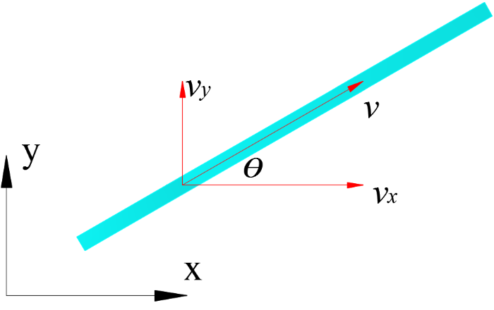
Figure 2.
Decomposition of superficial velocity
2.2.2. Grout Modulus and Viscosity
During the grouting process, the modulus and viscosity of the grout increase nonlinearly under the influence of hydration. Experimental study shows that the Young’s modulus and the viscosity of grout varied gradually:
Where ${{E}_{g}}\left( t \right)$ is the Young’s modulus of the grout, ${{\mu }_{g}}\left( t \right)$ is the viscosity coefficient of the grout, ${{\mu }_{g0}}$ is the initial viscosity coefficient of the grout, and $t$ is the hydration time.
The permeability coefficient of the grout in soil within a certain time can be calculated by the following formula:
Where ${{k}_{g0}}$ is the initial permeability coefficient of grout in soil.
3. Model Setups and Validation
3.1. Model Setup
In order to study the propagation regularity of multiple-hole fracture grouting, a numerical model is set as Figure 3. The simulation domain is 16m × 9m. The model is under the condition of plane strain. The simulation area is discretized into 8000 element meshes, and the material properties of each element obey Weibull distribution. The amount and position of grouting holes can be changed so that different conditions of fracture grouting can be simulated. The grouting pressure is applied gradually. Fracture grouting at different depth can be simulated by adjusting the value of the vertical load. The upper boundary is free, and the other three boundaries are fixed. The input parameters of soilare tabulated in Table 1.
Figure 3
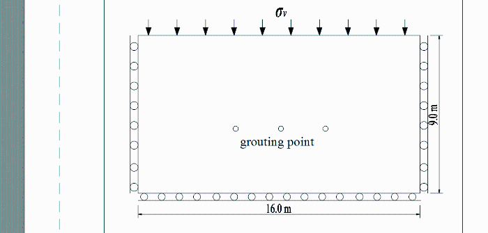
Figure 3.
Numerical model
3.2. Validation of the Approach
In order to verify the reliability of the numerical model, we carried out a field fracture grouting test. The project took place in a thermal tunnel using fracture grouting to compensate the ground loss. After the grouting was completed, the site is excavated to expose the grout veins around the grouting hole. At the same time, numerical simulations were carried out using the parameters of field soil. The grouting depth is 3m and the parameters of soil in fieldare given in Table 2.
Table 2. Parameters of field soil
| Soil | Height/m | Density/(g/cm³) | Young’s modulus/MPa | Cohesion/kPa | Friction angle (°) |
|---|---|---|---|---|---|
| Filled soil | 1.6 | 1.8 | 10.6 | 25.0 | 20.5 |
| Clay | 6.0 | 1.98 | 8.0 | 15.0 | 20 |
Figure 4(a) is the image of grouting vein revealed after excavation, and Figure 4(b) is the grouting vein numerically simulated. By comparing the two pictures, we can find that the simulation result is highly similar to the excavation result. This shows that the numerical method can be used to simulate the fracture grouting process in the soil. We can also find that there are many branches distributed relatively even around the grouting hole when the grouting depth is 3m. This is because the stress distribution is relatively uniform and the stress difference is small when grouting depth is small.
Figure 4
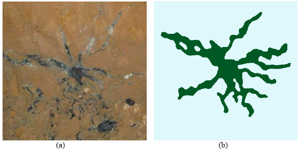
Figure 4.
(a) Grouting veins observed after excavation;(b) Grouting veins of numerical simulation
4. Numerical Simulation Results
In order to investigate the propagation regularity of multiple-hole simultaneous fracture grouting, three sets of simulations are presented here. These three sets of simulation are the basis for the study of multiple-hole simultaneous fracture grouting theory.
4.1. Simulation of Single-Hole Fracture Grouting
The grouting hole in this simulation was set in the depth of 5m, and the final grouting pressure is 0.6MPa. The grouting pressure was increased by 300 steps, and the increment of each step is 2kPa. After reaching the preset grouting pressure, the injection continues to grout 200 steps.
4.1.1. Propagation Process of Single-Hole Fracture Grouting
The propagation process of fractures and grout veins are shown in Figure 4. At the beginning of fracture grouting, the injection pressure is not enough to fracture the soil. Once the injection pressure reached and exceeded 400kPa, initial fracture was generated in verticaldirection, as shown in Figure 5(a). As the grouting pressure increased to 460kPa, secondary fractures originated and expanded at an angle to vertical direction,as seen in Figure 5(b). As the grouting pressure continued to increase, the grout veins continue to expand outward and new branches appear at the location closer to the surface, as shown in Figure 5(c) and 5(d). The simulation results indicate that the initial fracture is usually in vertical direction while the secondary fractures is not strictly horizontal but inclined.
Figure 5
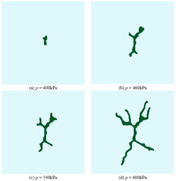
Figure 5.
The grout propagation process of single-hole fracture grouting
4.1.2. Vertical Displacement During Fracture Grouting
In order to investigate the variation of the ground displacement during the fracture grouting process, we monitored the vertical displacement of several measuring points in the model. Figure 6 shows the curve of vertical displacement versus time in the whole grouting process. The measuring points are respectively arranged at positions of 1m, 1.5m, and 2m above the grouting holes.
Figure 6
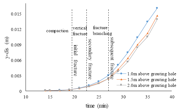
Figure 6.
Development of vertical displacement during grouting
It can be seen from the figure that the closer to the grouting hole, the greater the vertical displacement is; this phenomenon becomes more obvious as the grouting time changes. The displacement curve of the three measuring points is similar. In the compaction stage before the initial fracturing, the vertical displacements are very small and almost unchanged. As the initial fracturing occurs, the vertical displacement increases but is not obvious. The vertical displacement begins to increase significantly as the secondary fracturing occurs. The subsequent fracture causes the vertical displacement to increase at a faster rate. From the whole process, the vertical displacement grows faster after the secondary and subsequent fracturing occurs. This is because the expansion of the oblique grout vein branched is the main influencing factor of the increase of vertical displacement.
4.2. Double-Hole Simultaneous Fracture Grouting
Double-hole grouting is the simplestcase of multiple-hole grouting. The research of double-hole simultaneous fracture grouting is the basis for studying multiple-hole simultaneous fracture grouting.
4.2.1. Grouting Vein Morphology of Double-Hole Fracture Grouting
Four different hole-spacing weresethere: 1m, 2m, 4m, and 6m. The simulation results of double-hole simultaneous fracture grouting are shown in Figure 7. When the two holes are simultaneously grouted, the grouting holes interact with each other and the morphology of the grout vein is very different from that of a single hole. It can be seen from the four pictures that the grout vein branches between the two holes are deflected when the two holes are simultaneously grouted. The smaller the spacing of the grouting holes, the larger the deflection angle, and the easier to form horizontal branches.
Figure 7
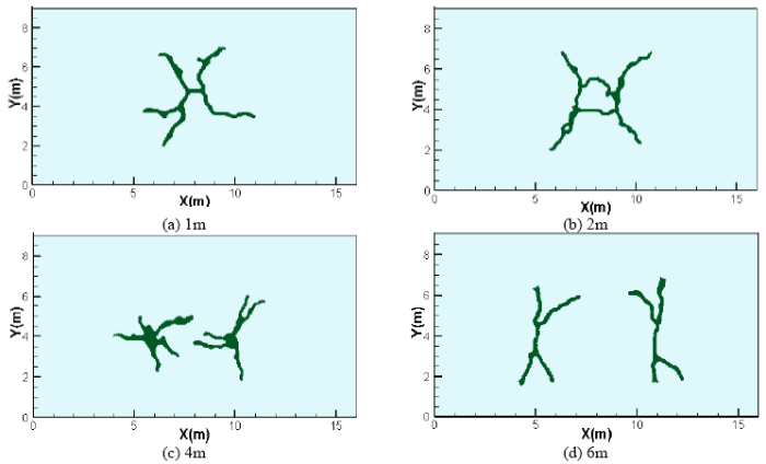
Figure 7.
Grouting veins morphology of different grout-hole spacing
When the spacing of the grouting holes is 1m, horizontal fracture quickly occurs and connects the two grouting holes. If the two holes are sealed effectively, the slurry veins will continue to expand outward. When the distance of the grouting hole is 2m, the branches between the two grouting holes are attracted to each other, and the propagation direction is gradually deflected to be close to the horizontal direction. When the grouting hole is increased to 4m, the fracture of the two grouting holes is respectively expanded at the beginning. When the fractures expand into the interaction area, the expansion direction is deflected. When the spacing of the grouting holes reaches 6m, the mutual interference between the two holes is weakened, and the fractures between the two holes are only deflected at a small angle.
The simulation results of double-hole simultaneous fracture grouting indicate that:
$\cdot$ The area between the two holes is affected by the stacking effect of the stress field of each hole, which interferes with the propagation of the adjacent grout veins. This interference is beneficial to the formation of horizontal grout veins.
$\cdot$ Simultaneous fracture grouting trend to form horizontal grout veins which are helpful in forming grouting curtain and realizing the better uplift effect
$\cdot$ The spacing of the grouting holes has a significant effect on the grout propagation when the two holes are simultaneously grouted, and it is easier to form the intersection and overlap of the grout veins when the hole spacing is small.
$\cdot$ There is mutual induction between adjacent groutvein branches cause them to propagate toward each other.
4.2.2. Propagation Process of Double-Hole Fracture Grouting
Take the working condition in Figure 7(c) as an example; we studied the grout propagation process of double-hole simultaneous fracture grouting. The spacing of the grouting holes is 4m, and the grouting pressure of each hole is 0.6MPa. We describe the minimum principal stress variation process and grout propagation process in Figure 8.
Figure 8
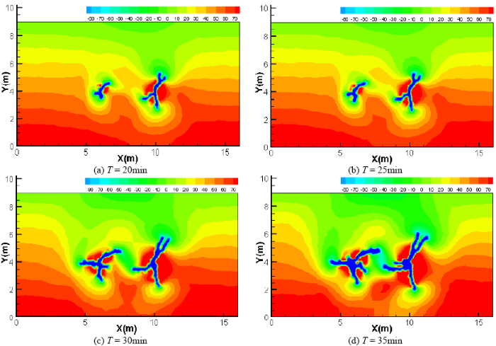
Figure 8.
Grout vein propagation process and variation of minimum principal stress during double-hole simultaneous fracture grouting
The grout vein started to propagate until nearly 18 minutes after the beginning of grouting. The initial fracture occurred in the nearly vertical direction. As the grout veins propagate, the soil around the grouting hole and on both sides of the grout vein is compacted so that the direction of minimum principal stress in the stratum changes gradually, as shown in Figure 8(a). Since the fracture expands perpendicular to the direction of the minimum principal stress, the direction of grout vein propagation also changes, as shown in Figure 8(b) and (c). As the crack tip between the grouting holes gets closer, the induction of the tip becomes more and more obvious, and the cracks begin to attract each other, as shown in Figure 8(d).
When the fractures between the holes are far apart, the change of the direction of the minimum principal stress is the main cause of the deflection of the grout propagation direction. As the fracture tip approaches, the mutual attraction of the fracture tip increases, causing the crack direction to deflect further and expand toward each other.
4.2.3. Vertical Displacement of Double-Hole Fracture Grouting
Here, we still take the case of a grouting-hole spacing of 4m as an example to analyze the lifting effect of double-hole simultaneous fracture grouting. The vertical displacements of the ground surface were recorded separately when the two grouting holes are separately grouted and simultaneously grouted, as shown in Figure 9. With single hole grouting, the vertical displacement of the stratum gradually decreases from the central position of the grouting hole to the two sides. It can be seen from the curve that the surface vertical displacement caused by simultaneous grouting is larger than the sum of the displacements caused by the separate grouting of the two holes. The horizontal grout vein formed when the two holes are simultaneously grouted improves the lifting effect.
Figure 9
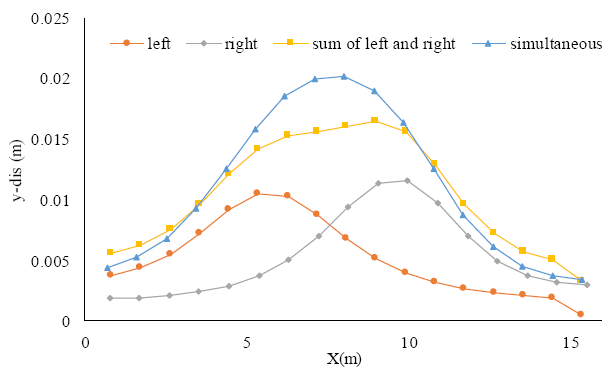
Figure 9.
Surface vertical displacement of single and double-hole simultaneous fracture grouting
4.3. Three-Hole Simultaneous Fracture Grouting
Three-hole simultaneous fracture grouting with a grouting-hole spacing of 2m and 3m was simulated. The simulation results are shown in Figure 10. The propagation regularity of three-hole simultaneous grouting is similar to double-hole grouting. Both will promote the deflection of grout propagation direction as well as the formation of horizontal grout vein. Moreover, the spacing of the grouting holes has significant effect on the grout propagation. The smaller the spacing of the grouting holes, the more obvious the stress interference between the holes, as seen from Figure 10. When the grouting-hole spacing is 3m, the initial fracture is along the vertical direction while the secondary fracture is in horizontal direction. When the grouting-hole spacing is 2m, the initial fracture is not strictly vertical or horizontal. This is because simultaneous grouting reduced the stress difference between the minimum and maximum principal stress.
Figure 10
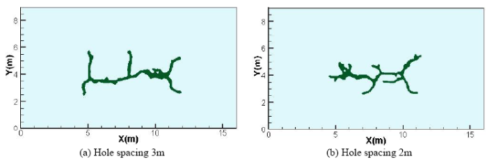
Figure 10.
Grout vein morphology of three-hole simultaneous grouting
5. Conclusions
The objective of this research was to improve understanding of the propagation process of simultaneous fracture grouting. In this study, a numerical model was used to simulate the propagation process of multiple-hole simultaneous fracture grouting. The propagation regularities of single-hole fracture grouting, double-hole simultaneous fracture grouting, and three-hole simultaneous fracture grouting were investigated.
$\cdot$ In the case of single-hole grouting, the initial fracturing direction is usually vertical and the secondary fracturing is not absolutely horizontal but inclined. The vertical displacement of the ground begins to increase rapidly since the secondary fracturing.
$\cdot$ When multiple holes were injected simultaneously, fractures among grouting holes might change their propagation direction and form horizontal grout veins. It is easier to form a closed grouting curtain when the multipleholes are grouted simultaneous.
$\cdot$ The spacing of the grouting holes has an important effect on the grout propagation, the smaller it is The greater the stress interference. It can even change the direction of the initial fracturing of adjacent holes.
$\cdot$ The uplift displacement produced by multiple-holes simultaneous fracture grouting was larger than the sum of uplift displacements when each grouting hole separately grouted.
In this paper, we showed the influence of grouting-hole amount and grouting-hole spacing on the propagation process and the grout vein morphology, which is a new aspect of this study. Although more research will be necessary, the work presented here can predict the propagation regularity and grout morphology qualitatively during multiple-hole simultaneous grouting.
Acknowledgements
This work was financially supportedby the National Key R&D Plan of China (No. 2017YFC0805400).
Reference
Analytical Model for Fracture Grouting in Sand
,”
Using Fracture Grouting to Lift Structures in Clayey Sand
,”
Grouting Techniques for the Unfavorable Geological Conditions of Xiang'an Subsea Tunnel in China
,”
DOI:10.1016/j.jrmge.2014.07.005
URL
[Cited within: 1]

One of the major challenges during subsea tunnel construction is to seal the potential water inflow. The paper presents a case study of Xiang'an subsea tunnel in Xiamen, the first subsea tunnel in China. During its construction, different grades of weathered geomaterials were encountered, which was the challenging issue for this project. To deal with these unfavorable geological conditions, grouting was adopted as an important measure for ground treatment. The grouting mechanism is first illustrated by introducing a typical grouting process. Then the site-specific grouting techniques employed in the Xiang'an subsea tunnel are elaborated. By using this ground reinforcement technique, the tunneling safety of the Xiang'an subsea tunnel was guaranteed.
Penetration Radius and Pressure Attenuation Law in Fracturing Grouting
,”
Fracture-Fracture Interaction During Grouting
,”
Effect of Hole Group Grouting in Confined Aquifer and its Field Experiment
,”The hole group grouting theory indicates that the diffusion range of the anterior grout will affect the diffusion range of the posterior grout,there will be a pressure gradient raising band of ground water formed at the boundary of consolidated anterior grout due to diffusion of the posterior grout,leading to flow of the grout to the place with less pressure. During the design of grouting,the intersection of diffusion radius of two neighbor holes is only an ideal state,which explains why the single row hole grouting could not give full grouting curtain. Compared with single row hole grouting,the multiple row hole grouting can form full curtain easier,which is superior to single row hole grouting due to hole group grouting effect. During multiple row hole grouting,the outer ring of holes should be grouted first,followed by inner ring of holes. A field experiment was carried out in a grouting work for a shaft of a coal mine in west China,the change of pressure in grouting hole and the water inflow in detecting hole during grouting were monitored. The results show that for single row hole grouting,there was high pressure zone inside the ring and low pressure outside the ring,it would be easy for the grout flew from high pressure zone to low pressure zone. The grouting effect of double row hole grouting is better than that of single row and for the multiple row hole grouting,the sequence is grouting for outer ring first,then for the inner ring.
Theoretical Study of Repetitive and Multiple Holes Grouting
,”
DOI:10.3969/j.issn.1000-0879.2004.03.007
URL
[Cited within: 1]
Aiming at the cylinder grouting manner, this paper studied repetitive grouting and multiple holes grout- ing for osmotic grouting, put forward some valuable theo- retical equations of grouting in rock mass. It can be used to instruct design and construction of grouting engineering in site.
Theoretical Study of Osmotic Grouting in Rock Mass
,”
Discussion: Laboratory Investigation of Multiple Grout Injections into Clay
,”
Laboratory Investigation of Multiple Grout Injections into Clay
,”
An FEM/VOF Hybrid Formulation for Fracture Grouting Modelling
,”
DOI:10.1016/j.compgeo.2014.02.002
URL
[Cited within: 1]
A numerical model using a hybrid formulation of a finite element method (FEM) coupled with the volume of fluid (VOF) technique to simulate the fracture grouting processes in soils is described. The numerical model considered the couplings of the stress distribution, with two-phase fluid flows, and the mesh element damage. The hardening of grout in soil is described by a time-dependent Young modulus and viscosity. Crack initiation, branching, propagation, and grout vein growth in homogeneous and heterogeneous soils can be numerically reproduced. Although the method is developed particularly for simulating fracture grouting, the processes of compaction grouting and permeation grouting can also be numerically simulated. Some grouting cases have been simulated with results similar to the experimental results. This further confirms the adequacy and the power of the numerical approach.
Coupled Analysis of Flow, Stress and Damage (FSD) in Rock Failure
,”
DOI:10.1016/S1365-1609(02)00023-0
URL
[Cited within: 1]
Rock is a heterogeneous geological material that contains natural weakness of various scales. When rock is subjected to mechanical loading, these pre-existing weaknesses can close, open, grow or induce new fractures, which can in turn change the structure of the rock and alter its fluid flow properties. Experimental results provide strong evidence that rock permeability is not a constant, but a function of stresses and stress-induced damage. A flow-stress-damage (FSD) coupling model for heterogeneous rocks that takes into account the growth of existing fractures and the formation of new fractures is proposed herein. Implemented with the Rock Failure Process Analysis code (F-RFPA 2D), this FSD model is used to investigate the behaviour of fluid flow and damage evolution, and their coupling action, in samples that are subjected to both hydraulic and biaxial compressive loadings. The modeling results suggest that the nature of fluid flow in rocks varies from material to material, and strongly depends upon the heterogeneity of the rocks.
