


1.Introduction
According to the diversity of satellite-launching demands, different kinds of upper-stages oflaunch vehicles have been developed. Some upper-stages can be used to carry several satellites into space orbits of different altitudes, while others can be used to deploy several satellites at different orbit positions. Nearly all these upper-stages oflaunch vehicles use great thrust force enginesfor navigation and gesture controlling, and these enginesareusually started up several times in the space orbit. During the space working time of the engine, the upper-stage is exposed to a space vacuum and cold environment, and its after-body is heated by exhaust plume and non-regenerative cooling nozzles. The exhaust plume heating has two forms: high-temperature gas radiation and reversed flow convection.
Regarding the numerical computation of base heating environments, it is well known that the continuum Navier-Stokes equations can provide an accurate physical model for the flow of great thrust force engines working on the ground and in the powered ascent, and direct simulation Monte Carlo (DSMC) has been used frequently for the flow simulation of minor thrust force engines working in space orbit. In recent decades, DSMC has been a mature technique for rarefied flow simulation.
In 2004, Wang et al. of Shanghai Jiaotong University simulated the plume flow field of rocket enginesin a vacuum environment by DSMC with the variable soft ball model (VSS) [1]. In 2009, Li et al. of the National University of Defence Technology used the model proposed by Gallisto solve the force and heat interaction between gas molecules and solid particles, demonstrating the mechanism of momentum and energy transmission in the progress of the interaction [2]. In 2011, Tang et al. of Beijing University of Aeronautics and Astronautics simulated the plume flow field ina vacuum environment using the decoupling N-S/DSMC method [3]. In 2015, Li et al. adopted the DSMC method to simulate the plume flow field of high altitude solid rocket motors[4]. In 2017, Ding et al. of Shanghai Jiaotong University used the DSMC method to simulate the plume flow field of high altitude solid rocket motors, taking into account the phase transformation process of solid particles [5].
The study of the thermal environment at the bottom of rockets mainly involves the acquisition of total heat flow, including convection heat flow and radiation heat flow. In the uncoupled algorithm, the convection data are obtained by analyzing the plume field of the rocket motor, and the radiation heat flow data are obtained by analysing the gas radiation transmission.
In 2004, Dong et al. of Harbin Institute of Technology adopted the RMC method instead of the traditional DSMC method to simulate heat radiation transmission in participatory media, and they achieved good results [6]. In 2005, Qi et al. of Shanghai JiaotongUniversity adopted the RMC method to simulate the infrared radiation characteristics of lobed nozzle/mixer plume [7]. In 2009, Yang et al. of Shanghai Jiaotong University adopted the RMC method to simulate the base heating environment of the secondary-stage of one launcher and obtained the changing trends of bottom heat flow with height [8]. In 2012, Li et al. of Nanjing University of Science and Technology investigated the effects of the alumina particle phase change process and a small amount of carbon soot on the radiation field using the RMC method [9]. In 2016, Sun et al. adopted the DSMC method to simulate the flow field of one rocket’s third-stage motor, and the RMC method was adopted to simulate the radiation heat flow received at different locations and compare the experiment results [10].
Although there are many computational studies on flow field and radiation, it is seldom individually used for great thrust force engines working in space orbit because of the limitation of computing efficiency and the memory usage.
In this paper, to increase the reliability of base heating prediction and thermal protection methodology,the numerical analysis of baseheating for upper-stage of launch vehicles with great thrust force engines working in a vacuum space is performed, the N-S equations and DSMC are coupled for this continuum/rarefied flow simulation, and the RMC method is used for radiation simulation. The results of the convective heat flux of plume, radiative heat flux of plume, and nozzle are given respectively. The total exterior heat flux conditionsof the different typical positions at the base of the upper-stage are obtained for designing the elaborate thermal protection system. The verification of this method is carried out by the comparison of the computed data and the measured data of the flight third-stage of one launch vehicle.
2. Modeling and Numerical Method
2.1.Convective Heating of Plume
In this paper, the plume includes the continuum flow region, slip flow region, transition flow region, and free molecule flow region at the same time. For different flow regions, different models are in application. In the continuum flow region, the frequency of collision between different molecules is far greater than the frequency of collision between molecules and walls; the gas motion can be described by N-S equations, the Fourier heat transfer equation, and the Fick mass diffusion equation. In the slip flow region, the continuous medium is still in domination, so theabove equations are still in application, but the phenomena of velocity slip, temperature jump, and heat slip can be observed. In the transition flow region, the molecular free path has the same magnitude as the characteristic dimension of flow, and the collision between molecules and walls should be considered as the collision between different molecules. Because the behaviour of incoming molecules is relevant to the walls and the reflected molecules may change the motion direction of incoming flow and the quantities of incoming molecules to the wall, the continuous medium hypothesis is not proper, and the Boltzmann equation is more suitable to describe the rarefied flow motion. In the free molecule flow region, the molecular free path is far greater than the characteristic dimension of flow, and only the collision between molecules and walls should be consideredwhile the collision between different molecules can be ignored. The DSMC method was put forward by Bird in the 1970s to solve the rarefied gas flow dynamics problems, and it has been popularly used since the 1980s. It was reported that Boyd,Campbell, and Nelson used the DSMC method for numerical simulation of rarefied expansion flow. To verify the application of DSMC in space plume, Boyd et al. also compared the computed data and the measured data of space plume in 1991 and 1992 [11-12]. Oh and Hastings used the quasi-neutrality cell particles-direct simulation Monte Carlo (PIC-DSMC) method to simulate the space plume of the Holtz propeller of flight vehicles[13]. Gimelshein et al. put forward a discrete model of multi-atom molecules’ energy transport usingthe rotation/vibration model and translation model. George and Boyd used a coupled method of CFD-DSMC for the simulation of plume in a vacuum space to save the computing time [14].
In this paper, the altitude of the new upper-stage working-orbit in the space is 200-1000km. Nitrogen tetroxide (N2O4) anddimethylhydrazine (UDMH) are used as propellants. The nozzle is cooled by the regenerative system and the radiative way, and the temperature of the radiative-cooling nozzle body is 1450K. The outlet combustion gas is a mixture of H2O,CO2,CO,N2, and H2. The propulsive force is 5000N. Because of the high rate of propellant flow, the plume in the adjacent region of the nozzle outlet is a continuum flow where the density and the pressure is higher; however, the plume far away from the nozzle and the plume in the reversed flow region is rarefied flow because of the high vacuum,so the reasonable technical route is to make different models for different kinds of flow. In this paper, the scheme is to solve the N-S equation in a finite difference way, coupled with DSMC of gaseous mixtures to obtain the convective heat flux of the plume. The three steps are taken as follows:
Step1 In the continuum flow region, the plume is modelled in the FLUENT software for the Navier-Stokes approach. By solving the N-S equation in a finite difference way, the numerical simulation of the nozzle inlet flow and the continuum flow of the plume can be realized.
In this study, the new upper-stage uses the swing singe-nozzle engine with great thrust force, the swing angle is ±25, and the hypothesis is that the plume is circumferential homogeneous distribution, so a two-dimensional symmetric model of the inner moulding surface of the nozzle is made, as shown in Figure 1. The symmetry axis of the nozzle is set to be the axial boundary, and the throat cross section of the nozzle is set to be the pressure inlet boundary of the flow.The total temperature, the total pressure, and the static temperature of the throat cross section are given as fixed numerical values. The length of the flow computing domain is 25 times the outlet radius of the nozzle, and the environment is set to be the pressure outlet boundary. In this study, the pressure is given according to an altitude of 200km. The gas flow in the nozzle is assumed to be one-dimensional thermal insulation isentropic flow, the flow is homogeneous compositing and steady, and the viscous property can be ignored.The mole percent of the gas component is constant, that is, the flow is assumed to be chemical frozen flow. Because the plume changes severely in the centrum, the mesh adjacent to the axis of the nozzle is in subdivision, as shown in Figure2. The flow is compressible turbulent flow, so the two-equation k-ε model using the explicit coupled algorithm is chosen.
Figure1.
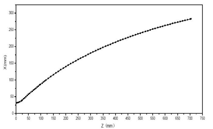
Figure 1.
The inner moulding surface of the nozzle
Figure2.
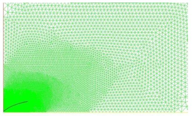
Figure 2.
The computing domain of the plum
Figures 3-9 show the contour results of the Mach number distribution, the pressure distribution, the velocity distribution, the density distribution, the temperature distribution, and the streamline distribution of the plume, respectively.
Figure 3.
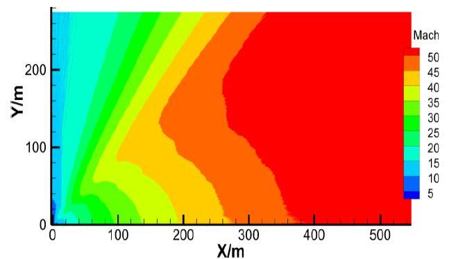
Figure 3.
The Machnumber distribution contour of the plume
Figure4.
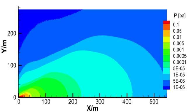
Figure 4.
The pressure distribution contour of the plume
Figure 5.
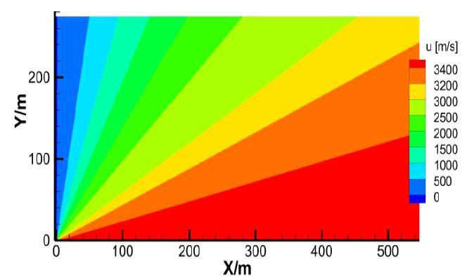
Figure 5.
The axial velocity distribution contour of the plume
Figure 6.
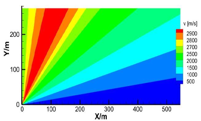
Figure 6.
The radial velocity distribution contour of the plume
Figure 7.
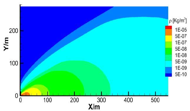
Figure 7.
The density distribution contour of the plume
Figure 8.
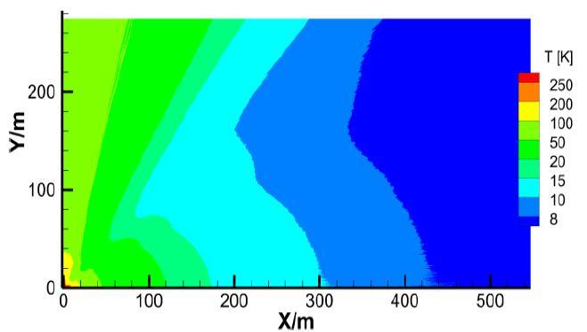
Figure 8.
The temperature distribution contour of the plume
Figure9.
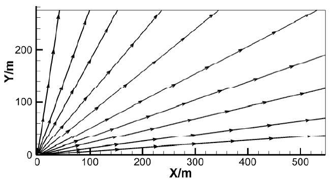
Figure 9.
The streamline distribution contour of the plume
Step2 According to the local Knudsen number (Kn), the boundary between the continuum flow and the rarefied flow is determined, and then this boundary would be the particle inlet of the DSMC model for simulation of rarefied flow.
The Knudsen number is defined as the ratio of the gas molecular mean-free path to the characteristic length scale: $Kn=\lambda /l$, where $\lambda$ is the gas molecular mean-free pathgiven by $\lambda =m/(\sqrt{2}\pi {{d}^{2}}\rho )$ and $l$ is the characteristic length scale (the nozzle outlet diameter in this article), $m$ is the molecular mass, $d$ is the molecular diameter, and $\rho$ is the flow density.
The flow region criterion put forward by Qian is taken in this paper:
·$Kn<0.01$no-slip continuum flow region
·$0.01<Kn<0.1$ slip flow region
·$0.1<Kn<10$ transition flow region
·$Kn>10$ free molecule flow region
In this paper, $0.1\le Kn$ is used as the criterion for determining the boundary between the continuum flow and the rarefied flow.
Step3 In the rarefied flow, the DSMC model of molecular dynamics is used to compute the rarefied plume and the reversed flow. Then, according to the different typical positions at the base of the new upper-stage, the convective heat flux is computed respectively.
The DSMC method put forward by Bird is now widely applied in engineering [15]. It is based on physics practice and uses a large number of simulation particles to represent numerous real gas atoms or molecules. It is a numerical method thatemploys the concepts of probability theory and statistics to analysenon-continuum gas flows. The simulation particles’ motion, collision, and energy transmission are controlled by the probability theory, and during each time step, the changes of the simulation particles’ position coordinates, velocity, and inner energy are recorded. Finally the macroparameters of rarefied flow are obtained through the statistic of the simulation particles’ motion behaviours in each cell.
In this paper, the hypothesis of DSMC computation was made as follows: a. the particle collision is binary collision; b. the rotation energy of the molecule is considered, whereas the vibration energy and the chemical non-equilibrium effect are ignored; c. the plume is steady flow, and the initial incoming velocity of the sampling molecule is randomly drawn according to the Maxwell velocity distribution pattern; d. the particles are seenas variable-diameter hard spheres.
Through Steps1 and2, the inlet boundary of the DSMC model is determined. It is an annulus surface of the nozzle outlet(0.295m≤R≤0.32m) and a cone surface whose coning angle to axis of nozzle is 65°. The simulation particles include five components of combustion gas, which are N2,H2O,CO,CO2, and H2. The DSMC computing domain is shown in Figure 10. The boundary conditions are set as follows: a. Z=0m, X=1.8m, and Y=1.8m are vacuum boundaries, some simulation particles going through which would be considered as escaping from the plume flow; b. X=0m and Y=0m are symmetry boundaries, some simulation particles arriving at which would have mirror reflections; c. the other boundaries including the nozzle and the base surfaces of the new upper-stage all are scattered reflection boundaries. If the DSMC method is used for the simulation of rarefied gas flow, the space step should be smaller than the molecular mean-free path, and the time step should be smaller than the local mean time of molecular collision. In this study, to enhance the computing efficiency, the space step is meshed by the geometric progression method, and the time step is represented as$\Delta \tau \text{=}3\times {{10}^{\text{-}7}}$s. The meshes are shown in Figure 10. The technological process of DSMC is shown in Figure 11, including the initialization, simulation of particles, boundary setting, adjustment of particles’ serial numbers, computation of collision, and statistics of macroscopic flow characteristics.
Figure 10.
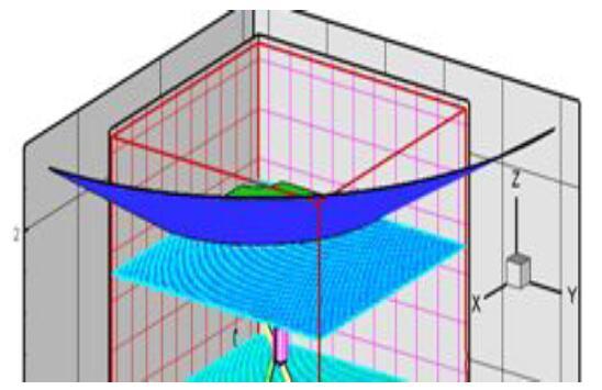
Figure 10.
The DSMC model domain and meshes
Figure 11.
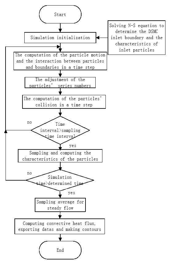
Figure 11.
The technological process of DSMC
2.2. Radiative Heating of Plume and Nozzle
The engine nozzle of the new upper-stage is cooled by the regenerative system and the radiative way. The radiative-cooling nozzle bodyis the majority, and its temperature is 1450K. The typical positions at the base of the upper-stage are heated by the plume convection, the plume radiation, and the nozzle radiation.
In this paper, the reversed Monte Carlo method (RMC) is proposed to calculate the plume radiation and the nozzle radiation at the same time, as shown in Figure12. The simulation is taken through the following two steps: a) to reversely follow the trail of the beam and to solve all scattering events during the trail according to the radiation transmission reciprocity principle, the luminous beam is emitted from the radiation-received surface until the it is absorbed or escapes from the flow; b) the trail of the beam is followed from the beam-absorbed point again to the radiation-received surface, and during this process, the radiation from the beam-absorbed point to the radiation-received surface will be recorded. This method is very suitable for radiation computations, as the radiation-received surface is far smaller than the radiation source, by which the calculating efficiency can be increased. In this paper, the plume of the great thrust force engine expands extremely in the vacuum space and the scale of the plume and the high-temperature nozzle is greater than that of the typical positions’ surface at the base of the upper-stage, so the RMC method is applicable.
Figure12.
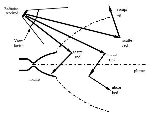
Figure 12.
The process of the RMC method
To use the RMC method, the heat radiation meshed model should be established according to the flow characteristics, and at the same time the motion behaviours of the radiation beams and the plume boundaries should be modelled by mathematics equations. In this paper, a three-dimensional cylinder radiation model is employed. The inner meshes of the cylinder are shown in Figure 13. The engine nozzle is modelled according to the wall outline, and the wall temperatures are respectively given for the different bodies cooled by different ways. The gas radiation belongs to the medium radiation, which has the intensive spectral selection character and the capacity character. In this paper, nitrogen tetroxide (N2O4) and dimethylhydrazine (UDMH) are used as propellants. The heat radiations of the combustion gas are mainly distributed in the infrared spectral coverage, which for different components is especially strong at different special wavelength, such as 2.7μm and 6.3μm for H2O, 4.3μm for CO, and 4.7μm for CO2. These three components are considered in this study. The narrow spectral band model is employed, the computing wavelength scope is 2 ~ 200μm, the total number of wave bands is 178, the collision broadening effect and the Doppler broadening effect of the spectral beam are considered, and thus the mean absorbing coefficient of the gas component in the narrow spectral band is obtained. In this paper, Fortran is used to establish the RMC computing code.
Figure 13.
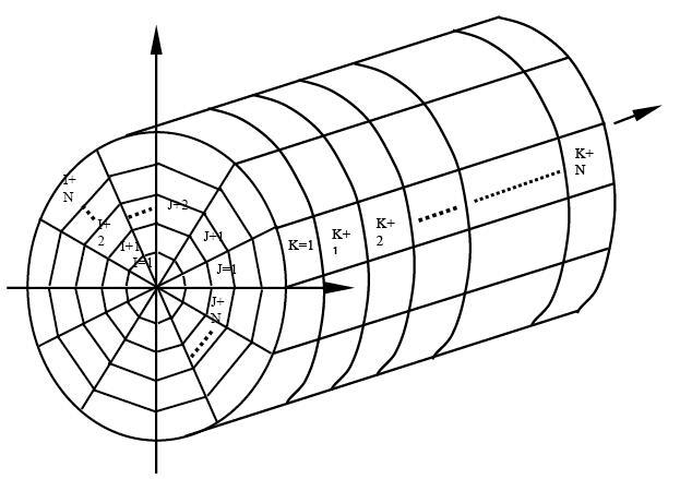
Figure 13.
The inner mesh of the cylinder model
3. Results and Discussions
For the new upper-stage, the total heat fluxes of the different typical positions at the base are a very important design basis for the new thermal protection system, which includes three kinds of heat fluxes: the convective heat flux of the plume, the radiative heat flux of the plume, and the radiative heat flux of the nozzle. The results are listed inTable 1, and the typical positions are shown in Figure 14.
Table 1. The heat fluxes results of the typical positions
| Serial number of the typical position | Heat flux(kW/m2) | |||
|---|---|---|---|---|
| Radiative heat flux of the nozzle | Radiative heat flux of the plume | convective heat flux of the plume | Total heat flux | |
| 1 | 10.9 | 0.224 | 0.01 | 11.13 |
| 2 | 15.6 | 0.162 | 0.21 | 15.97 |
| 3 | 17.7 | 0.155 | 0.39 | 18.25 |
| 4 | 9.8 | 0.172 | 0.50 | 10.47 |
| 5 | 12.96 | 0.182 | 1.14 | 14.28 |
| 6 | 12.87 | 0.157 | 1.38 | 14.40 |
| 7 | 8.7 | 0.193 | 0.47 | 9.36 |
| 8 | 12.04 | 0.144 | 0.24 | 12.42 |
| 9 | 5.76 | 0.312 | 0.95 | 7.02 |
| 10 | 4.82 | 0.232 | 1.09 | 6.14 |
Figure14.
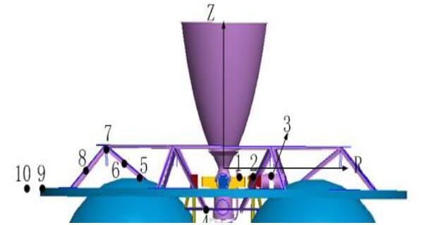
Figure 14.
The typical positions at the base of the new upper-stage
During the working time in space, the nozzle of the engine needs to swing, and the swing angle is ±25°, so the base heating environment of the swing engine is also calculated using the above mentioned method. The results are compared and listed in Table 1.It can be seen that the heat fluxes are greatly influenced for most typical positions except numbers 8, 9, and 10 by the swing engine. When the engine nozzle swing approaches some typical positions, the plume convective heat fluxes of these positions become greater, 1-2 times the results seen in Table 1, and the nozzle radiative heat fluxes become 20% greater than the results in Table1. The plume radiative heat fluxes do not change much.
4. Evaluations
In the 1970s, many theoretical analyses and ground wind tunnel experiments were carried out on the thermal environment at the bottom of the take-off stage of the American TITAN III rocket. The thermal radiation and convective heating of the single-nozzle and the multi-nozzle state were investigated.Kramer compared the results of theoretical analysis with those of ground experiments conducted in the Arnold Center for Engineering and Development. The theoretical model was verified and optimized by these ground experiments [13,16], the cost of which were very expensive.
Since the 1980s, with the development of computer technology, the numerical simulation of rocket motor plume has been used more and more widely. Flight experiments that replaced the ground test have been usually used for verification. The US space shuttle began its maiden voyage in 1981, ended it in 1984, and has completed five missions since then. NASA has done a great deal of work to measure the thermal environment of the shuttle bottom and compare the measured data with the predicted data to verify the simulation model[17-19].
In this paper, the flight experiment is carried out to evaluate the numerical simulation method. The base heating environment of the third stage of a flight launch vehicle is predicted by the method of this paper. The engine can also swing, and the swing angle is ±10° different from that of the engine in this paper. The propellants are the same, and the thrust force is 40kN. The base structure is broader than that of the new upper-stage. In the flight experiment, two heat flux sensors arelaid respectively at two typical positions at the base, and the normal of sensing face is parallel to the axis of the nozzle. The flight remote measured data curves are shown in Figures 15-16, and the measured data curves fluctuate because of the engine’s swing. The comparison of the computed data and the measured data is shown in Table 2, and the position of the number 2 sensor is closer to the nozzle. It can be seen that the predicted data is in good agreement with the measured data. The simulation method in this paper is verified by this flight demonstration. It proves the validity of the numerical simulation method in this paper.
Figure 15.
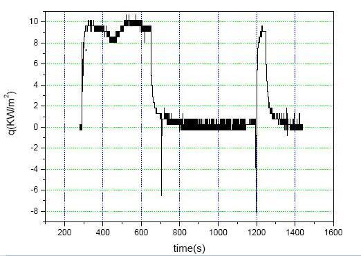
Figure 15.
The measured heat flux curve of number1 sensor
Figure 16.
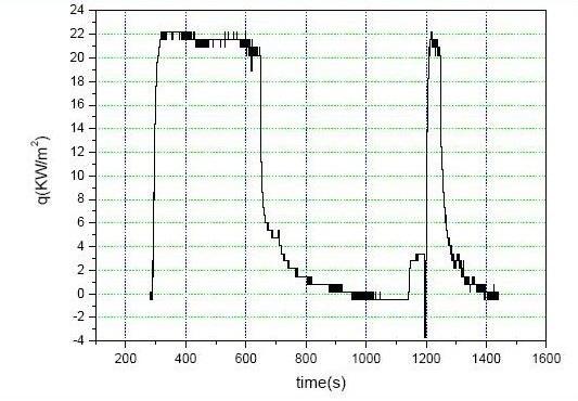
Figure 16.
The measured heat flux curve of number2 sensor
Table 2. The computed total heat flux and the measured total heat flux
| Serial number of the heat flux sensor | the computed total heat flux (kW/m2) | the measured total heat flux (kW/m2) | Percentage error |
|---|---|---|---|
| 1 | 11.6 | 5.6~10.1 | 14.9% |
| 2 | 22.6 | 16.7~22.3 | 1.3% |
5. Conclusions and Future Work
Forthe numerical analysis of base-heating for the new upper-stage of launch vehicles with great thrust force engines working in vacuum space, this scheme solves the N-S equations through a finite difference way coupled DSMC method of gaseous mixtures to obtain the convective heat flux of the plume.The RMC method is used to obtain the radiative heat flux of the plume and the nozzle. This scheme increases computing efficiency and achieves high accuracy in flight demonstration, so the results obtained in this paper are reliable for designing a new thermal protection system of the new upper-stage.On the basis of this elaborate base heating prediction, the weaknesses of the thermal protection can be found and the elaborate thermal protection can be realized, so the reliability of base heating prediction and thermal protection methodology can be increased.Some conclusions are drawn as follows:
·The velocity of the plume expansion in vacuum space is very high, and the majority of plume is rarefied flow.The plum radiative heat flux is low, as is the density and the pressure of the reversed flow. The plume convective heat flux is also not too great.
·The nozzle radiation effect on the base of the new upper-stage is an important factor for thermal protection designing.
·The thermal environment of the swing engine is very different from thatof the non-swing engine, and the numerical simulation of and experimentson swing engine base-heating will be deeply studied in future work.
Reference
“Dsmc Simulation of Plume Backflow from Bipropellant Attitude Control Engine”
,
DOI:10.1023/B:JOGO.0000006653.60256.f6
URL
[Cited within: 1]

Direct simulation Monte Carlo (DSMC) method in combination with the variable soft sphere (VSS) model was used to simulate vacuum plume backflow of N2O4/MMH. The parameters of the nozzle exit were gained from nozzle flow simulated by DSMC method. Comparison with those of previous work by others shows that the results of this paper are believable. The present results show light gases are more possible to enter the backflow zone.
“Two-Way Coupled Model for Rarefied Multiphase Flow”
,
DOI:10.1007/978-0-387-74660-9_12
URL
[Cited within: 1]

Based on the DSMC method,a two-way coupled mechanical and thermal model for high-altitude two-phase rarefied flow is presented with considering of particles' micro flow properties.An approach of DSMC is developed for multiphase flow in the transitional regime of rarefied gas.Simulations are performed for the verified case and the results show that the model agrees closely with the momentum and energy transfer mechanism.
“Investigation on Boundary Conditions in Decoupled N-S/DSMC Method for Vaccum Plume Simulation of Thrusters”
,
“A Numerical Method for Simulation Rarefied Two Phase Flow”
,
“Simulation of High Altitude Solid Rocket Plume based on DSMC Method”
,
“Computation of Radiative Heat Transfer in Participating Media using Backward Monte Carlo Method”
,
“Reverse Monte Carb Simulation on Infrared of Lobed Nozzle Mixer Plume”
,
“Numerical Simulation on Secondary Launcher Exhaust Plume Base Heating,”
“Influences of Phase Transition and Carbon Soot Impurity on the Radiative Properties of Alumina Particle Flow”
,
“Numerical Simulation and Flight Test Validation of a Launch Vehicle Altitude Engine Exhaust Plume Base Heating”
,
“Numerical and Experimental Investigations of Rarefied Nozzle and Plume Flows of Nitrogen,”
DOI:10.2514/6.1991-1363
URL
[Cited within: 1]
Numerical and experimental investigations are performed for the rarefied flow of nitrogen through a small nozzle which is expanded into near-vacuum conditions. Two different numerical studies are undertaken: the first employs a continuum approach in solving the Navier-Stokes equations, and the second employs a particle approach through use of the direct simulation Monte Carlo method (DSMC). The experimental investigation concerns the measurement of pressure, using a Pitot tube, in the nozzle exit plane and near-field of the plume. Comparison of the experimental and numerical data at the nozzle exit reveals that the DSMC technique provides the more accurate description of the expanding flow. It is discovered that the DSMC solutions are quite sensitive to the model employed to simulate the interaction between the gas and the nozzle wall surface. It is concluded that the simplistic fully diffuse model is quite satisfactory for the present application.
DeWitt,“Experimental and Numerical Investigations of Low-Density Nozzle and Plume Flows of Nitrogen,”
DOI:10.2514/3.11247
URL
[Cited within: 1]
http://arc.aiaa.org/doi/abs/10.2514/3.11247
“Evaluation of Thermal Radiation from the TITAN III Solid Rocket Motor Exhaust Plumes,”
DOI:10.2514/6.1970-842 URL [Cited within: 2]
“Simulation of Nozzle Plume Flows using a Combined CFD-DSMC Approach,”
DOI:10.2514/6.1999-3454 URL [Cited within: 1]
“Molecular Gas Dynamics and the Direct Simulation of Gas flows, ”
“TITAN III Convective Base Heating from Solid Rocket Motor Exhaust Plumes, ”
DOI:10.2514/6.1972-1169
URL
[Cited within: 1]
react-text: 231 We report progress in the development of a model-based hybrid probabilistic approach to an on-board IVHM for solid rocket boosters (SRBs) that can accommodate the abrupt changes of the model parameters in various nonlinear dynamical off-nominal regimes. The work is related to the ORION mission program. Specifically, a case breach fault for SRBs is considered that takes into account burning a... /react-text react-text: 232 /react-text [Show full abstract]
“Development of Space Shuttle BaseHeating Methodology and Comparison with Flight Data,”
in
“Space Shuttle Base Heating”
,
“BaseHeating Prediction Methodology used for the Space shuttle,”
