


1. Introduction
At the beginning of the establishment of space stations, “Zarya”, the first space cabin, was launched by Russia on November 20, 1998 [1]. Space stations act as a platform for human beings to observe the earth and study astronomy and bio-science [2]. The lifecycle of a space station ranges from 10 years to 15 years on average. During this period, random faults may happen on any type of device. In this case, on-orbit maintenance is a very effective solution. On-orbit maintainability is regarded as a very important tool to extend the lifecycle of space stations, ensuring the safety of astronauts and lowering the maintenance costs [3-5]. On-orbit maintenance activity of International Space Station is shown in Figure 1.
Figure 1.
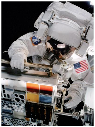
Figure 1.
On-orbit maintenance activity of the International Space Station
Maintenance tasks are not equal to maintenance operation. A maintenance task always starts from the detection of the fault until the function recovery and completion of the task [6]. Engineers should perform maintenance design, analysis, and verification to ensure the process before the vehicle is launched [7], while maintainability verification acts as the critical step during the entire process of maintenance. Figure 2 presents the maintenance workflow and design projects.
Figure 2.
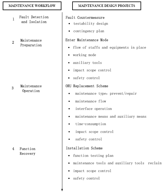
Figure 2.
Work flow and design projects of the on-orbit maintenance
It can be broadly justified whether the quality and quantity targets of the maintenance work are compliant with relevant requirements [8]. Nowadays, several methods of maintainability verification have been studied and used, including analysis validation, simulation analysis, ground simulated testing, and on-orbit flight testing [9]. A proper method of maintainability verification depends on several factors, including the features of the spacecraft, the requirements of the maintenance, and the development of the project.
This paper embarks on the mission of the China manned space station. It proposes the by-step classification on-ground testing methodology after reviewing and comparing the existing maintenance validation methodologies. Meanwhile, it also establishes a zero-gravity simulation separated validation platform that accommodates the internal and external cabin ORU. In addition, it enhances the feasibility, availability, and economical efficiency of the work of maintainability verification.
2. Requirement Analysis of Maintainability Verification Task
2.1. Requirement Analysis of Verified Objects
Maintainability verification is a tool to verify whether the maintenance work can suffice the requirements of the key performance indicator. Verified objects are always referred to as the whole products with the designated feature and can be maintained on-orbit.
To ensure the safety and reliability of the spacecraft during its long working period on-orbit, the maintainability verification of a manned space station must resolve the following two major issues.
One issue is enormous verified devices. Given the occasional failure of electronic products, as well as the abrasion and stuck of institutional products, it is common to put the on-orbit maintenance functionality on the design of important device and function that include GNC (Guidance Navigation Control), energy, environmental, and thermal control, as well as information management and astronaut residence support. There are different impacts and maintenance timing even between the same types of ORUs. To the electronic device, the validation must be separated due to the different related downstream equipment. To the fluid pipeline equipment, the validation also has to be separated because of the layout. Different layouts mean different visualization and accessibility. Therefore, the quantity of ORUs for an independent-flight-spacecraft can be up to hundreds, which means there will be thousands of ORUs on the space station. Strictly, verification for each ORU cannot be substituted for other ORUs.
The second issue is the difficulty in testing and verification. It is a challenge to maintain the ORU including a single board of electronic products, fluid pipeline equipment, institutional products, equipment with precise installation, and large external cabin ORU. The maintenance should be verified thoroughly on the ground, which should take the requirements for the astronaut and manipulator into consideration as well as the complexity of the operations and environment restrictions [10]. It should be mentioned that verification on the ground is not equal to equipment assembly. The order of equipment assembly is prioritized by the comfortability of the operation. Meanwhile, for an aircraft in orbit, many of the key equipment cannot be shut down. It is more important to keep the station working than to make the operations convenient.
All figures should be numbered with Arabic numerals (1, 2,
Figure 3.
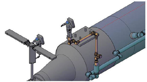
Figure 3.
Large external cabin ORU maintainability requires two astronauts and a manipulator assistant
Accordingly, while designing the on the ground maintainability testing method and plan, factors including category, quantity, interface form, layout, and the challenges of on-orbit maintenance the designer should be considered to ensure reasonable project planning. To avoid fundamental changes in the product design and layout in the final project phase caused by maintenance plan adjustment, it is important to arrange the typical ORU verification at the very beginning, which usually is ORU of energy, environmental, and thermal control products as well as worse layout equipment.
2.2. Requirement Analysis of Verified Items
In general, hierarchy of ORU can unfold in three levels, including product, subsystem, and system (aircraft). The validation of the product level relies on mechanical, electric, fluid, gas, and thermal interfaces, as well as the maintenance scheme of the product. The validation of the subsystem level relies on its working mode, maintenance tool, impact, and time consumption, as well as interfaces between this product and others, which belong to the same subsystem. The validation of the system level focuses on breakdown isolation, maintenance working mode setting, maintenance flow, system recovery, ORU transfer, maintenance impact of the whole aircraft, and maintenance tools arrangement.
Compared with the validation of the product level, verified items of the subsystem, even the system level, are obviously much more complex, involving breakdown isolation, separation of electricity and information, maintenance mode shift in-and-out of the aircraft platform, as well as maintenance operations, support, and time consumption. Therefore, verified items can be classified into some types. One type proves the ORU maintenance process, operation design and space, tools, and time consumption. The typical method is the flume experiment. The other type of verified items proves the default location, power supply and information separation design, maintenance working model, and scope of maintenance impact, and it usually combines with the integrative test.
2.3. Requirement Analysis of Verification Environment
The environment needed by on-orbit maintenance relies on a weightless environment and workplace.
The weightless environment is the critical factor to be considered during on-ground maintenance verification. Due to the power of the acting force and counter-acting force, astronauts must use a handle and stopper while performing maintenance work. It is shown in Figure 4 that there are many handles and stoppers in the cabin that are throughout the whole activity area.
Figure 4.
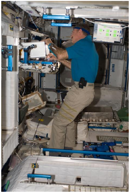
Figure 4.
Handles and stoppers in the cabin
The relative position between the astronaut and the apparatus, operation pit, and maintenance tools is different from the regular on-ground maintenance operation. In addition, because of the limited operation around the ORU, the coverage of the maintenance tool, standing position of astronaut, and operation scope are confined in a certain area. The serious limitations of activity space and visibility range are also applied to the maintenance program of external cabin ORU when the astronaut is in a spacesuit.
Therefore, when a maintenance verification plan is designed, it should simulate the scenario of human beings, apparatuses, and tools in a weightless environment to reflect the ORU layout environment, i.e., the astronaut visibility scope and activity area to ensure the testing result is the most similar as that in reality.
3. Analyses of Maintenance Verification Methods
To stimulate the weightless environment of astronauts and ORU, on-ground testing methods have been extensively studied at home and abroad, among which such testing can be divided into mock tests and digital simulating tests. Digital simulating tests include computer picture simulation and VR simulation [11-12]. Mock tests include neutral buoyancy tank, parabolic flight, gas floating platform, hanging maneuver, drop tower, 1-g simulation, and hypobaric chamber [13-14]. This paper shows the comparison with the testing object, verified items, and the environment by some powerful methods.
As mentioned above, the quantity of ORUs for an independent-flight-spacecraft can be up to the hundreds. Almost all the ORUs should have their maintenance scheme under the cabin environment verified. If we use the maintenance verification methods in Table 1, long testing time consumption and excessive costs will not be avoided. Therefore, a proper on-ground maintenance verification method should be studied urgently to meet the requirements of the China space station.
Figures 5-7 show the different laboratory methods.
Table 1. Comparison of on-ground maintenance verification methods
| Method | Object | Item | Environment |
|---|---|---|---|
| 1-g simulation (low accuracy, low cost) | Verify different types of ORU; certain area representing whole layout | Maintenance operations | Normal environment, 3D activity space |
| Hypobaric chamber (low accuracy, low cost) | Testify parts of maintenance scheme | Partial maintenance operations, partial maintenance supporting | Low pressure environment, 3D activity space |
| Gas floating platform (high accuracy, high cost) | Microgravity maintenance scheme | Maintenance operations | Microgravity; 2D activity space |
| Hanging maneuver (high accuracy, high cost) | Broad testing objects, almost representing layout | Maintenance operations, maintenance time, partial maintenance support | Microgravity, 3D activity space |
| Neutral buoyancy tank (higher accuracy, higher cost) | Broad testing objects, fully representing layout | Maintenance operations, maintenance time, partial maintenance support | Microgravity, 3D activity space |
| Computer picture simulation (high accuracy, low cost) | Broad testing objects, almost representing layout | Maintenance operations, maintenance time | Microgravity, 3D activity space |
| VR simulation (high accuracy, low cost) | Broad testing objects, almost representing layout | Maintenance operations, maintenance time | Microgravity, 3D activity space |
Figure 5.
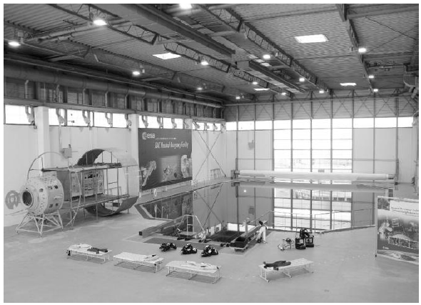
Figure 5.
Neutral buoyancy tank, ESA European Astronaut Center, Cologne, Germany
Figure 6.
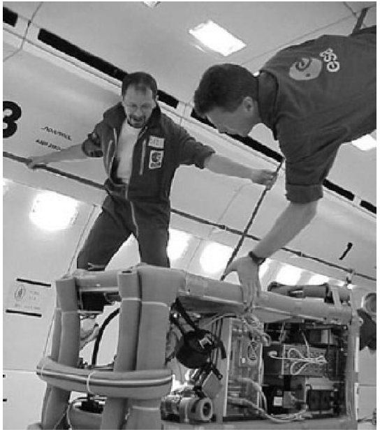
Figure 6.
ESA’s maintenance verification in Airbus A300 with microgravity environment
Figure 7.
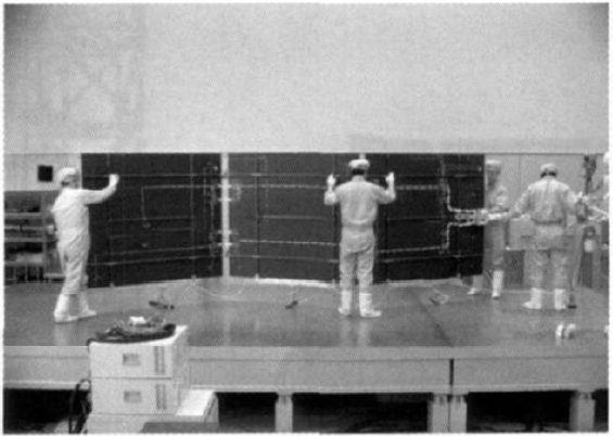
Figure 7.
Japanese solar array maintenance test on gas floating platform
4. Study of Maintainability Verification Methodology
4.1. Study of By-Step Classification On-Ground Testing Method
Regarding the analysis results of maintenance verification requirements, this paper proposes a by-step classification on-ground testing method to accommodate the maintenance programs of enormous and complex ORUs.
This by-step classification method is based on detailed analysis of the tasks, while classified by verified objects, verified items, and verified methods. It can optimize the accuracy, cost, and time consumption of on-ground tests by extended objects and items while choosing the most proper method mentioned in Chapter 3 step by step.
The by-step classification on-ground testing method includes four steps, as follows.
The first step is to focus on typical ORUs, which should have earlier phase verification. These typical ORUs are defined by curbing ORU maintenance type, interface, and the difficulty of identification, usually including energy equipment, information equipment, and fluid pipelines. Visibility and attainability can be verified in this step, which usually takes place throughout computer picture simulations [15].
The second step is to focus on ORUs with difficult operations, such as those with complex operations and narrow operating space, as well as large-scale equipment. Maintenance operations and the scope of impact can be verified in this step for ORU and its tools, which usually occurs throughout computer picture simulation plus on-ground testing (e.g. 1-g simulation, hanging maneuver), as shown in Figure 8.
Figure 8.
Figure 8.
Maintenance of ORU with difficult operations by hanging maneuver
The third step is to focus on all kinds of ORUs at least with complex operations and small operating space. Maintenance verifications are performed in the simulated cabin environment. The maintenance procedure, operation, time consumption, scope of impact, and certain part supporting can be verified in this step, which usually takes place throughout 1-g simulation, hanging maneuver, and VR.
The fourth step is to face as many ORUs of the space station as possible. All the verified items mentioned in Section 2.2 should be verified. The hanging maneuver, neutral buoyancy tank, VR, and other methods can be used.
Table 2. Four steps of by-step classification on-ground testing method
| 1st step | 2nd step | 3th step | 4th step | |
|---|---|---|---|---|
| Verified object | Different kind of product | Complex operating equipment, narrow operating space equipment, large-scale equipment | All kinds of ORU esp. Complex operation, small operating space based on simulated cabin environment | Maintenance operation and procedure for all kinds of ORU in cabin environment |
| Verified items | Visibility and attainability | Maintenance operation, maintenance tool, scope of impact | Maintenance procedure, maintenance operating, time consumption, scope of impact, certain part supporting | Maintenance procedure, operating design and space, tool, time; default identification, power supply and information separation design, maintenance working mode, scope of impact. |
| Verified method | Computer picture simulation | Computer picture simulation + on ground testing (1-g simulation, hanging maneuver etc.) | 1-g simulation, hanging maneuver, VR | Hanging maneuver, neutral buoyancy tank, VR |
| Product illustration | Preventive maintenance ORU, fluid loop equipment, external cabin ORU | Greater impact scope, passably meet visual and attainable requirement, specialized tools | Cover the verified object in 1st step and 2nd step. Can make adjustment with reference to the current layout. | To cover ORU as more as possible |
4.2. Simplified Partial Testing Platform
The verification of maintenance operation is the critical part of maintenance verification. It can mainly prove the ORU maintenance process, operating design, space, tools, and time consumption.
Based on the factors illustrated in Table 1, it is understood that the hanging maneuver and neutral buoyancy tank can simulate 3-D activities in the weightless environment with high accuracy but at a higher cost, which means it cannot perfectly meet the verification needs of the China space station. This paper proposes a simplified zero-gravity simulating partial testing platform that considers the adoptability, effectiveness, and cost of the lifecycle. It can verify the maintenance operation, space, and tools for the internal and external cabin ORU.
The zero-gravity simulating partial testing platform simplifies the internal and external cabin environment. The platform includes the internal cabin environment stimulated platform, external cabin environment stimulated platform, and zero-gravity hanging system for astronauts, products, and tools, as shown in Figures 9-11.
Figure 9.
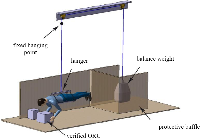
Figure 9.
Zero-gravity hanging system
Figure 10.
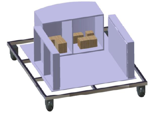
Figure 10.
Internal cabin environment stimulated platform
Figure 11.
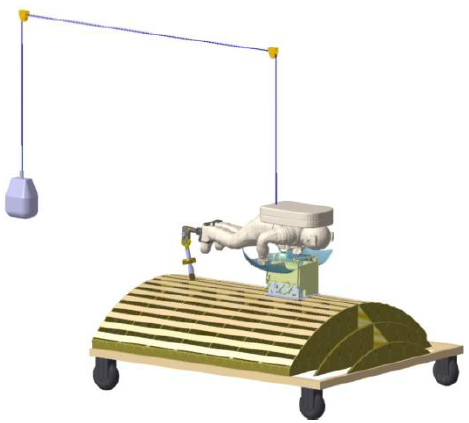
Figure 11.
External cabin environment stimulated platform
Figure 9 describes the zero-gravity hanging system. The system is designed as a passive balanced system, including a fixed pulley, tether, and balance weight. It has four degrees of freedom, which are upper and lower, front and rear, left and right, as well as rotational freedom.
4.3. Engineering Practice of Maintenance Verification
Different methods of maintenance verification have been used in the maintenance program for the China space station.
As expressed in Table 1, earlier phase verification should be arranged for typical ORUs of different kinds by computer picture simulation. Figure 12 shows the maintenance simulation of a lithium-ion battery. According to Figure 12, it can be concluded that the non-positive operation of ORUs has poor accessibility. Therefore, ORUs with non-positive operation should be verified one by one.
Figure 12.
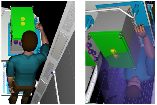
Figure 12.
Maintenance verification by computer picture simulation
Figure 13.
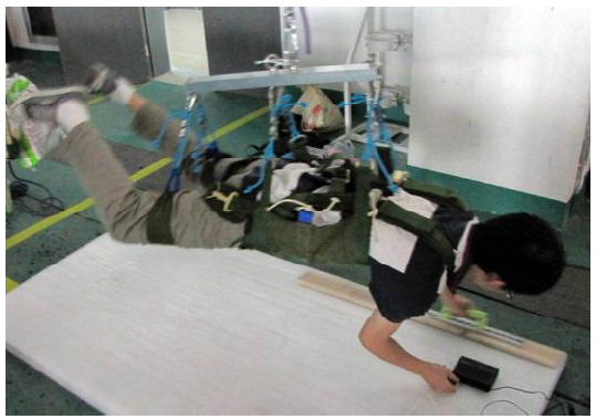
Figure 13.
Practice of zero-gravity simulating partial testing platform
Then, maintenance verifications in the simulated cabin environment can be arranged. It is not necessary to equip all real products (the same configuration as launched) at the beginning. Figure 14 shows the first round of maintenance operation verification in the internal cabin environment.
Figure 14.
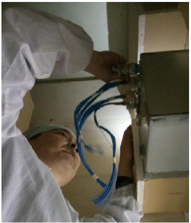
Figure 14.
First round of maintenance operation verification in internal cabin environment
After several rounds of improvement, the products with the same configuration launched can be equipped for testing. Then, the fourth step in Table 2 can be arranged to verify all the items using different tests and methods.
Acknowledgements
The work described in this paper was supported by a grant from the Shanghai Science and Technology Commission Excellent Technical Leader Program Project (No. 17XD1423500).
Reference
“International Space Station, ”
“Spacelab Technology Summary and Development Stratagem, ”
Spacelab is a kind of space vehicle which can execute multipurpose manned space science experiments.At present, there are two kinds spacelab in international space exploration field.One has the ability to implement missions in orbit independently, the other needs another spacecraft's support.Spacelab technology is important to the development of space station, which is also under developing by our country now.This paper presents approaches during international spacelab development, and illuminates our conceptions and schedule of spacelab development for the next step.
“On-Orbit Maintenance Operations Strategy for the International Space Station—Concept and Implementation, ”
DOI:10.1063/1.1357918
URL
[Cited within: 1]

The International Space Station (ISS) has an operational mission and profile that makes it a Logistics and Maintenance (L&M) support challenge different from previous programs. It is permanently manned, assembled on orbit, and multi-national. With this technical and operational challenge, a unique approach is needed to support the hardware and crew. The key is the integration of on-orbit and ground analysis, supply, maintenance, and crew training into a coherent functional process that supports ISS goals and objectives. To integrate all the necessary aspects of hardware and personnel to support on-orbit maintenance, a myriad of products and processes must be created and coordinated, such that the right resources are in the right place at the right time to ensure continued ISS functionality. This paper will familiarize the audience with ISS On-Orbit Maintenance (OOM) concepts and capabilities for different maintenance tasks and discuss some of the logic behind their selection. It will also identify the operational maintenance support responsibility split between the U.S. and the various International Partners (IPs).
“International Space Station Maintenance & Repair Group (MRG) In-Flight Maintenance Book ISS-4A, ”
“The Planning and Design for the On-Orbit Maintenance of Space Station, ”
in
“Multimedia Maintenance Manuals: International Space Station Applications for On-Orbit Maintenance Support, ”
DOI:10.1016/S0094-5765(02)00080-2
URL
[Cited within: 1]
Maintenance operations related to the elements of the ISS are very complex operations that have to take into account several aspects: the configuration of the elements, the operational capabilities, the timeline of the maintenance task, the tools and support equipment that has to be used and in general all the constraints induced by the on-orbit environment. In this sense, one of the most important aspects of the maintenance operations on ISS is the availability of all the different data related to the on-going task applied on very complex systems like the on-orbit modules are. Most of this data are contained in different databases related to different working groups and many times the essential data are scattered and must be retrieved from all these different sources. The utilization of a Multimedia Maintenance Manual can significantly improve the execution and the efficiency of the maintenance tasks on the ISS when these data are collected on a multimedial support and presented in conjunction with animated video sequences showing the task to be performed. The ISS Node 2&3 Program will be used as reference for the development of the Multimedia Maintenance Manual.
“Improving Maintenance Operations on the International Space Station, ”
DOI:10.1016/j.actaastro.2008.11.011
URL
[Cited within: 1]
The Special Purpose Dexterous Manipulator (SPDM), known as “Dextre”, is currently slated to launch in February 2008 for deployment on the International Space Station (ISS) as the final component of Canada's Mobile Servicing System (MSS). Dextre's primary role on the Space Station is to perform repair and replacement (R&R) maintenance tasks on robotically compatible hardware such as Orbital Replaceable Units (ORUs), thereby eventually easing the burden on the ISS crew. This burden on the on-orbit crew translates practically into crew time being a limited resource on the ISS, and as such, finding ways to assist the crew in performing their tasks or offloading the crew completely when appropriate is a bonus to the ISS program. This is already accomplished very effectively by commanding as many non-critical robotics tasks as possible, such as powering up and free-space maneuvering of the Space Station Remote Manipulator System (SSRMS), known as “Canadarm2”, from the Ground. Thus, beyond its primary role, and based on an increasing clarity regarding the challenges of external maintenance on the ISS, Dextre is being considered for use in a number of ways with the objective of improving ISS operations while reducing and optimizing the use of crew time through the use of ground control for various tasks, pre-positioning hardware, acting as a temporary storage platform to break an Extra Vehicular Activity (EVA) day into manageable timelines, and extending the physical reach and range of the Canadarm2. This paper discusses the planned activities and operations for Dextre an rationale for how these will help optimize the use of crew resources on the ISS.
“Study on Design and Verification Method of Space Station Maintainability, ”
To ensure the highly reliable and long time operation of the space station, methods of maintainability design and on-orbit servicing are applied on the Space Station. Based on the theory and engineering practice of maintainability, the demand analysis method according to the product characteristic was discussed in this paper. The calculation method for reliability under maintenance support was presented. System maintainability design should include the layout, power supply, information, fault detection and maintenance mode. According to the difficulty of repair, a four level repair strategy and the method for the ground test and simulation were proposed in this paper. It is a feasible approach to the space station system maintainability design.
“Training Astronauts using Three-Dimensional Visualizations of The International Space Station, ”
DOI:10.1016/S0094-5765(98)00188-X
URL
PMID:11541951
[Cited within: 1]
Recent advances in personal computer technology have led to the development of relatively low-cost software to generate high-resolution three-dimensional images. The capability both to rotate and zoom in on these images superposed on appropriate background images enables high-quality movies to be created. These developments have been used to produce realistic simulations of the International Space Station on CD-ROM. This product is described and its potentialities demonstrated. With successive launches, the ISS is gradually built up, and visualised over a rotating Earth against the star background. It is anticipated that this product's capability will be useful when training astronauts to carry out EVAs around the ISS. Simulations inside the ISS are also very realistic. These should prove invaluable when familiarising the ISS crew with their future workplace and home. Operating procedures can be taught and perfected. "What if" scenario models can be explored and this facility should be useful when training the crew to deal with emergency situations which might arise. This CD-ROM product will also be used to make the general public more aware of, and hence enthusiastic about, the International Space Station programme.
“Computer Aided Design and Graphics Techniques for EVA Analysis, ”
in
“Zero-g Aircraft Flight Method Research, ”
DOI:10.1016/S1872-2040(07)60059-0
URL
[Cited within: 1]
This paper introduces the zero-g aircraft parabolic fight technology.The motion and maneuvers of zero-g aircraft parabolic flight were discussed in the lecture.And using a model of certain aircraft as an example, the four phases of zero-g parabolic flight simulation are completed.The result demonstrates that through a series of parabolic maneuvers the test aircraft can result in 20~30 s periods of zero-g acceleration(actually around 10-2g).The method of the parabolic flight maneuvers can be used in the zero-g aircraft flight test.
“Experimental Study on the Dynamics and Control of a Space Robot with Experimental Free-Floating Robot Satellite (FFORTS) Simulators, ”
“Virtual Humans for Animation, Ergonomics and Simulation, ”
in
DOI:10.1109/NAMW.1997.609848
URL
[Cited within: 1]
The last few years have seen great maturation in the computation speed and control methods needed to portray 3D virtual humans suitable for real interactive applications. We first describe the state of the art, then focus on the particular approach taken at the University of Pennsylvania with the Jack system. Various aspects of real-time virtual humans are considered such as appearance and motion, interactive control, autonomous action, gesture, attention, locomotion, and multiple individuals. The underlying architecture consists of a sense-control-act structure that permits reactive behaviors to be locally adaptive to the environment, and a “PaT-Net” parallel finite-state machine controller that can be used to drive virtual humans through complex tasks. Finally, we argue for a deep connection between language and animation and describe current effects in linking them through the JacMOO extension to lambdaMOO
