


1. Introduction
The topology analysis of high-voltage network of coal mine is the basis of short-circuit current calculation and relay protection setting calculation, which requires accuracy, reliability and real-time. With the expansion of the mine power grid, the increase of network nodes and the complexity of the topology of the power grid, there are higher requirements in the reliability, real-time and openness of network connectivity analysis[1].
The commonly used topological analysis algorithm of high-voltage power network of coal mine mainly includes matrix method, search method, etc. Ref. [2] proposes to use node-branch association matrix to describe the topological structure of the grid, according to the “AND” and “OR” operation rules of Boolean vectors and the principle of node consolidation. The incidence matrix is modified and simplified to realize the identification topology of the power grid. In Ref. [3-5], the connection matrix of square method, sparse matrix processing technology and gauss elimination technique are applied to the topology analysis power grid based on matrix method and the matrix method is improved. Ref. [6] proposes a block network topology method, by introducing the concept of switch interval. The device model was abstracted into nodes and the node adjacency lists were established, according to the characteristics of the switch interval. A certain rule is set up to analyze the network block topology of the power network. When the topology of the power grid changes, the whole network topology update achieved by rebuilding the local network topology changes as well. Ref. [7] proposes object-oriented technology to abstract the grid model. The set of nodes that are connected together by closed switches is abstracted into bus, and the bus connecting the lines and transformers is abstracted into “electrical islands”. Ref. [8] proposes a system network topology analysis algorithm based on the generalized Kirchhoff current law. The new algorithm requires only a small number of switch states and carries out correlation calculation to achieve accurate division of electric islands. Ref. [9] proposes a layer search method for power grid supply routes based on the GIS-based visualization method. On this basis, the power grid flow calculation and load forecasting are carried out to realize the visualization of power supply path search and the intelligenceof the power grid analysis. Ref. [10] proposes a new real-time tracking algorithm that combines the bus as the node to traverse in whole power grid with the local update of the equipment unit. Ref. [11] proposes a drawing algorithm based on topology layering, which can realize the automatic generation of electrical wiring diagram of distribution network. According to the characteristics of high-voltage grid power supply system of coal mine, Ref. [12] constructed a topological analysis model for coal mine high-voltage power grids with single bus and multiple segments based on the incidence matrix, and achieved the topological identification of coal mine high-voltage grids.
Most of high-voltage power supply system of coal mine diagrams mentioned are the connection diagram of the switch and the bus. However, in some coal mines’ underground high-voltage power supply system diagrams, in order to complete the drawing of the underground high-voltage power supply system more intuitively, it uses the high-voltage output line shown in Figure 1.The drawing of the underground high-voltage power supply system diagram is completed through the direct alignment between high-voltage output line switch graphic element and high-voltage output line switch graphic element in the bus position of underground high-voltage power supply system. In the drawing process, the corresponding connection points are set on the high-voltage output line switch element and the high-voltage output line switch element respectively. When the two graph elements are close enough, the automatic alignment of the graph element is realized by the automatic capture algorithm. The capture process is shown in Figure 2, and the final result based on node alignment is shown in Figure 3.In the drawing of the completed underground high-voltage power supply system, there is no independent bus element. The existing topology analysis method of the high-voltage power grid based on the incidence matrix cannot directly analyze the topology of the above underground high-voltage power supply system and construct the topology model. In the completed underground high-voltage power supply system diagram, there is no independent bus element. The existing topological analysis method of high-voltage power grid of coal mine based on incidence matrix cannot directly topological analyze the above-mentioned underground high-voltage power supply system diagram and build a topological structure model.
Figure 1.
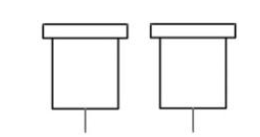
Figure 1.
The high-voltage outlet switch graphics
Figure 2.
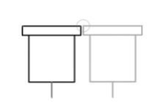
Figure 2.
Thehigh-voltage outlet switch elements for automatic capture
Figure 3.
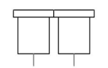
Figure 3.
Thehigh-voltage outlet switch elements which are automatically aligned
The network topology model of high-voltage power supply system of coal mine based on node coincidence and incidence matrix is proposed, which can easily complete the topology identification of the power supply network of the high-voltage power supply system, in this paper. It can realize the function of automatic short-circuit calculation and has characteristics of simple and high efficiency.
2. Adaptive Topology Analysis Model of High-Voltage Grid of Coal Mine based on Node Coincidence and Incidence Matrix
Set the power input line switch node of the high-voltage power supply system of coal mine, which refers to the input line switch node that is directly powered by the upper power supply department. Assuming that in the high-voltage power supply system diagram of coal mine, the number of outgoing switch nodes is S, the number of line nodes is T, the number of input switch nodes is N, and the number of contact switch nodes is U. By default, the multiplication of matrix elements and matrix elements is binary AND operation, and the addition operation of elements and elements is binary OR operation.
2.1. The Basic Correlation Matrix is Directly Generated According to the High Voltage Power Supply System Diagram of Coal Mine
2.1.1. Generate a Transverse Incidence Matrix a Between Output Line Switch Node and Output Line Switch Node
For the high-voltage power supply system of coal mine, the high-voltage output line switch is used as output line switch node. According to the connection relationship between the electrical equipment in the high-voltage power supply system diagram of coal mine, the transverse incidence matrix A of the output line switch node and the output line switch node is generated, and A is S
Step 1 The sequence number of the output line switch node i corresponds to the row number of the incidence matrix A, the sequence number of the outgoing switch node j corresponds to the column number of the incidence matrix A, and the elements of the i row and the j column of the incidence matrix A are represented by Aij.
Step 2 If the output line switch node i is adjacent to the output line switch node j, then Aij=1; if the output line switch node i and the output line switch node j are not adjacent, then Aij=1.
Step 3 Set the value of the element Aij to 1,which meansi equal j in the incidence matrix A.
2.1.2. Generate a Transverse Incidence Matrix B1 Composed of Contact Switch Nodes and Outgoing Switch Nodes
For the high-voltage power supply system of coal mine, the contact switch is used as the contact switch node, and the high-voltage output switch is used as the output switch node. According to the connection relationship between the electrical equipment in the high-voltage power supply system of coal mine, to generate horizontal incidence matrix B1 of the contact switch node and the output switch node, B1 is U
Step 1 The sequence number of contact switch node i corresponds to the to the row number of the incidence matrix B1, the sequence number of output line switch node corresponds to the column number of the incidence B1; and the elements of the i row and the j column of the incidence matrix B1 are represented by B1ij;
Step 2 If the contact switches node i is adjacent to output line switch node j, and the switch state of the interconnection switch node is closed, then B1ij=1; otherwise, B1ij=0
2.1.3. Generate an Incidence Matrix C Between the Output Line Switch Node and the Input Line Switch Node
For the high-voltage power supply system of coal mine, the high-voltage output line switch is used as the output line switch node, and the input line switch is used as the input line switch node. According to the connection relationship between the electrical equipment in the high-voltage power supply system of coal mine, to generate incidence matrix C of the output line switch node and the input switch node, C is S
Step 1 The sequence number of output line switch node i corresponds to the to the row number of the incidence matrix C, the sequence number of input line switch node j corresponds to the column number of the incidence C; and the elements of the i row and the j column of the incidence matrix C are represented by Cij.
Step 2 If the output line switch node i is supplied by the input line switch node j, and the switch state of the interconnection switch node of output line switch node and input line switch node is closed, then Cij=1; otherwise, Cij=0.
2.1.4. Generate an Incidence Matrix D on Line Switch Node and Output Line Switch Node
For the high-voltage power supply system of coal mine, the line is used as the line node, and the high-voltage output line switch is used as the output line switch node. According to the connection relationship between the electrical equipment in the high-voltage power supply system of coal mine, to generate incidence matrix D of the line node and the output switch node, D is T
Step 1 The sequence number of line node i corresponds to the to the row number of the incidence matrix D, the sequence number of output line switch node j corresponds to the column number of the incidence D; and the elements of the i row and the j column of the incidence matrix D are represented by Dij.
Step 2 If the line node i is supplied by the output line switch node j, and the switch state of the interconnection switch node of output line switch node j is closed, then Dij=1; otherwise, Dij=0.
2.1.5. Generate an Incidence Matrix E on Input Line Switch Node and Line Node
For the high-voltage power supply system of coal mine, the input line switch is used as the input line switch node, and the line is used as the line node. According to the connection relationship between the electrical equipment in the high-voltage power supply system of coal mine, to generate incidence matrix E of the input line switch node and the line node, E is N
Step 1 The sequence number of input line switch node i corresponds to the to the row number of the incidence matrix E, the sequence number of line node j corresponds to the column number of the incidence E. The elements of the i row and the j column of the incidence matrix E are represented by Eij.
Step 2 If the input line switch node i is supplied by the line node j, and the switch state of the interconnection switch node of input line switch node is closed, then Eij=1; otherwise, Eij=0.
2.2. Generate the Vertical Primary Power Supply Incidence Matrix MG
For the high-voltage power supply system of coal mine, according to the incidence matrix A, B1, C, E and D, calculate the vertical primary power supply incidence matrix MG of the output line switch node and the output line switch node; the specific steps are as follows:
Step 1 Generate a primary incidence matrix F of the output line switch and output line switch, which can be written as F=C
Step 2 Generate a primary vertical incidence matrix B3 of the output line switch and output line switch, which can be written as B3=B1T
Step 3 Generate the modified incidence matrix B, which can be written as B = A+B3
Step 4 Generate the incidence matrix G,which can be written as G=B
Step 5 If the incidence matrix G is equal to the incidence matrix F, executeStep6. Otherwise, the value of the incidence matrix G is assigned to the incidence matrix F; repeat Step 4.
Step 6 For the calculated matrix G, all elements which the line number equal to column number in the matrix G are set to 1. The matrix MG, which is the vertical primary power supply incidence matrix of the output line switch node and the output line switch node, is obtained.
2.3. Generate the Final Power Supply Incidence Matrix L and the Power Supply Incidence Matrix FC
For the high-voltage power supply system of coal mine, according to the incidence matrix B, C, E, D and MG, calculate the incidence matrix L of the output line switch node and the line nodeand the incidence matrix FC of the output line switch node and input line switch node. The specific steps are as follows:
Step 1 The incidence matrix H=MG
Step 2 The matrix MC = B
Step 3 The incidence matrix of output line switch and line node is L, which can be written as L=H
Step 4 The final power supply incidence matrix of output line switch and line node is FC, which can be written as FC=H
The power supply incidence matrix L reflects the power supply relationship between the output line node and the line node, and the power supply incidence matrix FC reflects the power supply relationship between the output line node and input switch node. Both provide a topology analysis model for subsequent automatic short-circuit calculation, and effectively realize the topology identification of high-voltage power network in coal mine.
3. Simulation Analysis
Figure 4 is a high-voltage power supply system diagram of coal mine. The high-voltage switch node drawn with the virtual line is in the open state, and the high-voltage switch node is drawn with the solid line is in the close state.Set the system reactance in the maximum operating mode and minimum operating mode of high-voltage power supply system of coal mine.The contact switch node number, input line switch node number, output line switch node number, and line node number are shown in Figure 4.The high-voltage switches numbered (1), (2), (3), (4), (5), (6), (7) and (8) are the input line switch nodes, of which (1) and (2) are the power input switch node; high-voltage switches numbered 1, 2, 3, 4, 5, 6, 7, 8, 9, 10, 11, 12, 13, 14, 15, 16, 17 are the output line switch nodes; the high-voltage switches numbered [1], [2], [3], [4], [5] are the contact switch node; the lines numbered <1>, <2>, <3>, <4>, <5>, <6>, <7> are the line nodes.
Figure 4.
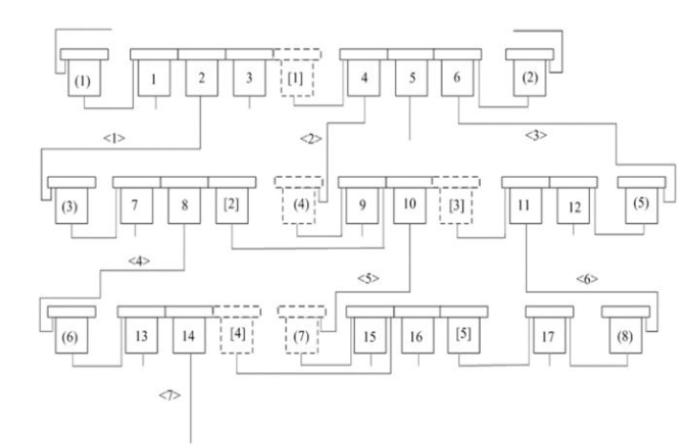
Figure 4.
The underground high-voltage power supply system
The proposed short-circuit calculation method for the underground high-voltage power grid is based on the node coincidence and incidence matrix, which is to complete the short-circuit calculation for the high-voltage power grid of coal mine shown in Figure 4. The specific steps are as follows.
3.1. Calculate the Incidence Matrix A
The incidence matrix A generated by the high-voltage power supply system of coal mine is expressed as Equation (1):
3.2. Calculate the Incidence Matrix B1
The incidence matrix B1 generated by the high-voltage power supply system of coal mineis expressed as Equation (2):
3.3. Calculate the Incidence Matrix C
The incidence matrix C generated by the high-voltage power supply system of coal mine is expressed as Equation (3):
3.4. Calculate the Incidence Matrix D
The incidence matrix D generated by the high-voltage power supply system of coal mineis expressed as Equation (4):
3.5. Calculate the Incidence Matrix E
The incidence matrix E generated by the high-voltage power supply system of coal mineis expressed as Equation (5):
3.6. Calculate the Incidence Matrix MG
The incidence matrix MG generated by the high-voltage power supply system of coal mineis expressed as Equation (6):
3.7. Calculate the Incidence Matrix L and FC
The incidence matrix L and FC generated by the high-voltage power supply system of coal mine is expressed as Equation (7):
3.8. Automatic Short-Circuit Calculation of High-Voltage Power Supply System of Coal Mine
For the high-voltage power supply system of coal mine, automatic short-circuit calculation of the high-voltage power supply system is completed based on the incidence matrix L and the incidence matrix FC; the specific steps are as follows:
Step 1 The resistance matrix Ris based on line node and line node; in matrix R, the corresponding elements of column i row j are represented by Rij. If the element of i row and j column are represented by Rij; if i =j, then the value of Rij is equal to the resistance Ri of the line with sequence number i; otherwise, Rij=0.The resistance matrix Ris expressed as Equation (8):
Step 2 The reactance matrix X on line node and line node; in matrix X, the corresponding elements of column i row j are represented by Xij. The element of i row and j column are represented by Xij; if i=j, then the value of Xij is equal to the resistance Xi of the line with sequence number i; otherwise, Xij=0. The reactance Matrix X is expressed as Equation (9):
Step 3 Assume that the W is T
Step 4 Calculate the Matrix LR and LX.The Matrix LR and LXis calculated by:LR = L
Step 5 When short-circuit occurs at the end of the line i, line i is controlled by the output line switch node i. Therefore, we find the corresponding row based on the position of the output line switch node i (row number) in the incidence matrix FC, then find the column number corresponding to all elements, which value is equal to 1. According to the obtained column number, find the corresponding input switch node set PP, which is the collection of all input line switch nodes that supply power to line i. If there are no power line switch nodes in the set PP, it means that line i has no power supply and does not perform short circuit calculation. If there are no power line switch nodes in the set PP, it means that line i does not have power supply, and not carry out short-circuit calculation. If there are power line switch nodes in the set PP, the node is represented by Y, which means that line i is supplied by power. Execute Step 6.
Step 6 According to the output line switch node i (number of row) , to find the corresponding row in matrix LR and matrix LX, then find the value of the corresponding element in that row, represented by TR and TX respectively.
Step 7 Assume that the system reactance under the maximum operating mode corresponding to node Y is represented by MAXX, add the value of TX to MAXX and assign the calculated result to TXMAX. Assume that the system reactance under the minimum operating mode corresponding to node Y is represented by MINX, add the value of TX to MINX and assign the calculated result to TXMIN.According to the average voltage UU and total resistance and total reactance of the line where the short-circuit point of the high-voltage power supply system is located, calculate the three-phase short-circuit current $I_{\max }^{(3)}$ in the maximum operating mode and the two-phase short-circuit current $I_{\min }^{(2)}$ in the minimum operating mode.
The three-phase short-circuit current $I_{\max }^{(3)}$ in the maximum operating mode is expressed as Equation (10):
The two-phase short-circuit current $I_{\min }^{(2)}$ in the minimum operating mode is expressed as Equation (11):
4. Conclusions
The traditional high-voltage power supply system of coal mine topology analysis model for high-voltage power supply system is mostly diagram of switch and bus. However, in the drawing process of underground high-voltage power supply system, the position of the bus is to complete the drawing of the underground high-voltage power supply system through the direct alignment between the high voltage outlet switch graphic element and the high voltage outlet switch graphic element. There is no independent bus graphic element, and the existing topology analysis method of the high-voltage power grid based on incidence matrix cannot complete topology analysis and construct topology model of the above underground high-voltage power supply system diagrams.
The network topology model of high-voltage power supply system of coal mine based on node coincidence and incidence matrix, which can solve the above problems effectively, is proposed in this paper. The simulation results show that the model can easily complete the topology identification of the power supply network of the high-voltage power supply system. On this basis, it can realize the function of automatic short-circuit calculation. It also has the characteristics of simple and high efficiency.
Acknowledgements
This work is supported by Scientific and Technological Breakthrough Plan of Henan province (No. 172102210274) & Key scientific research projects of institution of higher learning of Henan Province (No. 61405055).
Reference
“Study on Power Network Topology Analytic Algorithm,”
“A Novel Method for Power Grid Topology Identification based on Incidence Matrix Simplification,”
“Application of Improved Gaussian Elimination Algorithm in Power System Topology Analysis,”
“Determination of Network Topology by Fast Quasi-Square of the Adjacency Matrix,”
“Analysis of Network Topology by the Matrix Method with Sparse Matrix Techniques,”
“An Analysis on the Modeling of Partitioned Network Topology in a Power System,”
“A Graphic Database Base Network Topology and ITS Application,”
“A New Network Topology Analysis Algorithm based on Generalized Kirchhoff’s Current Law,”
“Research on Multi-Layer Search Method of Power Supply Path based on GIS,”
“An Efficient Algorithm Tracking of Topology for Distributed Networks and its Application,”
“An Automatic Generation Algorithm of Electrical Wiring Diagram based on Topological Hierarchy,”
“Self-Adaptive Calculation Method for Mine High-Voltage Power Grid with Single Bus and Multiple Segments Operation,”
