


1.Introduction
Due to special production, nuclear power stations have very strict requirements for safety and economy during production.In particular, third generation nuclear power units with million kilowatt capacities, which are highly developed, are now required to reach the advanced technical level of the thirdgeneration nuclear power on the basis of meeting relevant reliability requirements of the Utility Requirement Document (URD) and the European Utility Requirement (EUR).Forced unavailability not only influences economic indicators of nuclear power units, but also seriously threatens the safe operation of units.There are many factors that cause forced shutdowns, such as availability loss mainly due to systems being unable to work normally based on operation experience and system design.In this paper, the average number of forced shutdown days per year for EPR units is evaluated through the PAA method.
The EPR Nuclear Power Unit is the third generation nuclear power technology of the European PWR, which has the largest single unit capacity in the world.
2.Forced Unavailability Parameter
It is defined in the second sector of the second volume of the EUR that forced unavailable related parameters must be met in order to ensure the availability for the third generation of the nuclear power unit.The duration of forced shutdown of units≤5days/year(1.4%).Forced unavailability parameters are shown in Table 1.
Table 1. Forced unavailability parameters
| Category | Index description | Index value |
|---|---|---|
| Parameters of unplanned scram | Unplanned automated scram frequency | < 1 time/7000 critical hours |
| Duration of forced outage | ≤ 5 days/year (1.4%) | |
| Overhaul deferral due to major equipment maintenance or replacement | ≤ 150 days/20years |
3.PAA (Probabilistic Availability Assessment)
PAA (probabilistic availability assessment) is a method to evaluate the availability of plants.Take the system that causes unavailability during normal operation as a unit.By calculating the probability of occurrence and the unavailable time of the critical failure mode, make the unavailable target of the initial allocation become satisfied.Through feedback and optimization design, continuously upgrade the unit reliability level.The process of the PAA method is shown in Figure 1.
Figure 1.
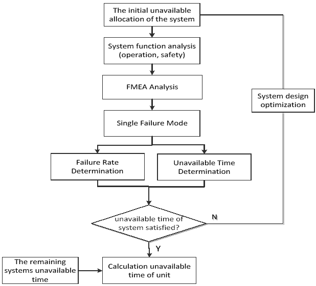
Figure 1.
Process of PPA method
According to FMEA, the PAA method is based on a system to select all the single and key failure modes that cause the shutdown of the unit under the normal power mode and calculates the unavailable time of the power unit that each key failure mode causes through the failure rate of the key failure mode and the mean down time (MDT).
4.System Brief Introduction
PAA is mainly used to evaluate the unavailability time of main system failures on the forced unavailability of power plants.
Taking the main steam and main feed-water system of EPR as an example, the main steps of PAA analysis are summarized as follows:
1) Function analysis of the system;
2) Fault mode and effect analysis;
3) Estimation of forced unavailability of power plants caused by system failures.
The main steam (nuclear island) and main feed-water system of EPR refer to the whole process from the main feed-water isolating valve to the main steam isolating valve through the secondary side of the steam generator.
It is the pivot of one and two circuits of the nuclear power plant.The main function is to transfer the heat from the primary coolant to the feed-water of the two circuits, generate steam in the steam generator to drive the turbine to generate power, and realize primary circuit and two-loop separation by the steam generator to ensure that the two-loop steam is free of radioactivity.
4.1.System Function
4.1.1.Operation Function
The operation functions (OF) of main steam VVP system:
$\cdot\$ OF1: Supply steam generated by SG to turbine and other steam users;
$\cdot\$ OF2: In the tests, thermal shutdown or low power operating conditions, the system transfers the thermal power of SG to the condenser (if available);
$\cdot\$ OF3: Exhaust steam through the VDA system during unit start-up and before hot shutdown conditions are reached;
$\cdot\$ OF4: Ensure the pressure and temperature rise rate of the steam line downstream of MSIVs are met during the heat shutdown of the unit during the heating pipe;
$\cdot\$ OF5: Condensate water from steam lines during unit start-up.
The operation functions (OF)of main feed-water system:
$\cdot\$ OF1: Feed water from high pressure feed-water heater system to SG;
$\cdot\$ OF2: Low pressure load regulating valve (LLCV) and full load regulating valve (FLCV) are used to control the flow of feed-water and maintain the level of SG in normal operation range;
$\cdot\$ OF3: Isolate SG in case of feed-water system failure to avoid overflowing of SG;
$\cdot\$ OF4: Above 20% of power rating, LLCV to keep open, FLCV to regulate the water flow;
$\cdot\$ OF5: At start-up and shutdown stages and below 20% power rating, only LLCV opens and adjusts feed-water flow.
4.1.2.Safety Function
The safety functions of the main steam VVP and main feed-water system are defined in the system design report, and three main safety functions are performed:
$\cdot\$ SF1: Reactivity control.
$\cdot\$ SF2: Residual heat discharge.
$\cdot\$ SF3: Radioactive material containment [4].
4.2.Periodic Test
The periodic test of main steam and main feed-water systems that will affect the forced unavailability of the unit:
$\cdot\$ PT1: Operational test of main steam isolation valve (partial closure test)
The test is conducted once a month and can be carried out after the main steam tube is heated or in reactor power operation mode. Each time a different master tube is selected, the valve is partially closed (10%) to verify the operation of the main steam isolation valve.
$\cdot\$ PT2: Partial closure test of feed-water isolation valve
The test is carried out every two months and can be carried out in reactor power operation mode and in addition to the state of feed-water flow regulated by the main feed-water small flow regulating valve. This test is used to check the operation of the main feed-water isolation valve when the feed-water isolation signal appears [5-6].
5.EPR Unit Application
5.1.Initial Forced Unavailability Distribution
The initial forced unavailability distribution provides some guidance data of systems thatcontribute to plant unavailability and is used for comparison after assessment.It is defined as: forced shutdown time of initial distribution for EPR units≤5days/year; initial forced shutdown time of NSSS and BNI≤3days.
Among them, according to the previous unit operation experience feedback, the unusable time of the main steam system and main feed-water system is 0.99 hours and 2 hours, respectively. Detailed system distribution valuesare shown in Table 2.
Table 2. Allocation of time for initial forced unavailability of main steam and main-feed water system
| Power plant system | Unavailable time (empirical feedback) | Allocated unavailable time (1.4%) | Historical experience/unavailability of distribution |
|---|---|---|---|
| VVP | 0.99 | 1.00 | 0.99 |
| ARE | 2.0 | 2.00 | 1.00 |
5.2.Failure Mode and Effect Analysis
5.2.1.Presuppositions
FMEA identifies failure modes of critical components for plant availability. The following presuppositions should be made:
$\cdot\$ Only analyze failures pertinent to unit power operation modes. As for conditions that are not pertinent to unit power operation, like unit condition under the condition of starting or shutdown, failures will not influence the forced unavailability of plants.
$\cdot\$ Only consider single failures of equipment including subsequent secondary failures.
$\cdot\$ Without considering unit shutdown caused by external factors: false operation and flooding.
$\cdot\$ Excluding hand-operated valves with diameter of pipeline≤25mm.
$\cdot\$ Without analyzing position sensors, which provide a limit switch of valve stem in the valve.
$\cdot\$ In-situ measurements will not influence plant availability and do not need to be considered.
5.2.2.FMEA Analysis of Main Steam Pipeline
1) An external leak.The external leakage of the main steam pipeline can be detected by the leakage detection system, and the leakage valve can be repaired without affecting the availability of the power plant. Therefore, the failure mode of external leakage may not be considered.
2)The main isolation valve (MSIV) refuses to close. The failure will result in partial loss of safety function of the main steam system. According to CPR1000 operating experience, if an MSIV control line is unavailable or one or more valves of the same function group refuse to close, the unit begins to withdraw to the NS / RIS-RHR mode within three days.
3)The main isolation valve MSIV was mistakenly closed. The failure will lead to the loss of part of the operation function of the system and the high steam pressure on the secondary side of SG. When the SG pressure is higher than the set value, the reactor shutdown signal will be triggered to ensure the fuel integrity and the coolant system integrity at the power level.
From the above analysis, failure modes of the main steam system that result in forced unavailability of plants are selected as shown in Table 3.
Table 3. Failure modes of VVP system
| Component ID | Component type | Failure mode |
|---|---|---|
| Main steam pipeline | Main steamisolation valve MSIV | Fail to close |
| Main steam isolation valve MSIV | Closed by mistake |
5.2.3. FMEA Analysis of Main Feed-Water Pipeline
1)Main feed-water regulating valves fail to regulate, which is the failure of the main feed-water control flow system that results in failing to regulate the water level of the steam generator SG’s secondary side.If the feed-water flow is high, the water level of SG will be too high, which may result in the overflow of steam generators and the automated shutdown of units.
2) Main feed-water isolation valve refuses to close, which will result in partial safety function loss of systems.There are two redundancy designs for this isolation valve, and one can conduct main feed-water isolation while another one cannot close failures.Based on the operation experience of CPR1000, when one feed-water isolation valve with full load has not been closed and cannot be closed in one column or a few columns, if the power is 20% over rated power, the power level of station units should be lowered to below 20% of the rated power within three days and the isolation valves with full load in each effected column should be closed.If this does not work, the power should remain 20% below rated power and one isolation valve with full load in each effected column should be closed at the same time and be repaired within three days.
3) Main feed-water isolation valve is closed by mistake, which will result in partial operation functions loss of systems and main feed-water isolation and lead to feed-water loss of SG and SG’s secondary side being unable to take out the heat;then, the temperature and pressure of SG’s primary side increase, and the scram signal is triggered.
From the above analysis, the failure modes of the main feed-water system that result in forced unavailability of plants are selected as shown in Table 4.
Table 4. Failure modes of ARE system
| Component ID | Component type | Failure mode |
|---|---|---|
| Main feed-water pipeline | Main feed-water regulating valve | Fail to regulate |
| Main feed-water isolation valve | Refuse to close | |
| Main feed-water isolation valve | Close by mistake |
5.3. Determine the Failure Rate
The failure rate of the critical failure mode determines the input condition for calculating the forced shutdown time. The failure rate of the component failure mode in PAA comes from different sources, and the detailed data sources mainly are:
$\cdot\$ Reliability data pertinent to PSA;
$\cdot\$ Operation experience of fourth circuit pressurized water reactors in France and Germany;
$\cdot\$ Expert judgement.
From operation experience, the hourly failure rate of component k’s failure mode jis calculated as below:
$\cdot\$ njk—During given time period T, times of component k’s failure j.
$\cdot\$ T—One reactor operation in one year within operation experience feedback.
$\cdot\$ NFk—Amount of component k in each French nuclear power plant.
$\cdot\$ NGk—Amount of component k in each German nuclear power plant.
$\cdot\$ HFP—Duration of operating with full power in each nuclear power plant per year.
The failure rate that is estimated and used during forced unavailability calculation of main feed-water system components is shown inTable 5.
Table 5. Failure rate of critical component failure mode
| Component code | Failure mode | Failure rate |
|---|---|---|
| Main steam pipeline | Refuse to close | 3.1×10⁻⁴ |
| Close by mistake | 1.9×10⁻⁶ | |
| Main feed-water pipeline | Fail to regulate | 2.8E-06 |
| Refuse to close | 3.0E-04 | |
| Close by mistake | 3.08E-07 |
5.4. Forced Overhaul Time Caused by Single Failure
Each system (operation or safety) might influence the availability of plants, and the unavailability types can be divided into direct shutdown, power reduction, and indirect shutdown (OTS) based on failure consequences. The way of calculating the plant unavailability time (UUi) caused by system“i” is shown below:
$\cdot\$ UUi=total amount of unavailability time caused by component k’s failure=∑(Xjk)
$\cdot\$ Xjk= (failure rate of component k) × (unavailability time caused by component k’s failure) =λjk×TUjk
The calculation methods of TUjk are described in detail inTable 6 based on unavailability types.
Table 6. TUjkCalculation methods of different unavailability types[7]
| No. | Unavailability type | Failure unavailability time | Failure unavailability probabilistic |
|---|---|---|---|
| 1 Category: direct shutdown | 1a: automated shutdown | TUjk = t100→0%PNshutdown+ tcondition+ tpreparation+ MTTR+ tre-identification+ treach100%PN | Xjk = λjk × TUjk |
| 1b: hand-operated shutdown | TUjk = t100→0%PNhand-operated+ tcondition+ tpreparation+ MTTR + tre-identification+ treach100%PN | ||
| 1c: hand-operated shutdown after power reduction | TUjk = α·tdiagnosis+ t100→0%PNnormal+ tcondition+ tpreparation+ MTTR + t re-identification + treach100%PN | ||
| 2 Second category: power reduction | 2a: maintenance during power reduction | TUjk = α·(MTTR + tre-identification) | |
| 2b: power reduction to next shutdown | TUjk =α·t diagnosis +t100→0%PNnormal+ tcondition + tpreparation+MTTR + t re-identification +treach100%PN | ||
| 3 Third category: OTS requirements | 3a: failures that cannot be repaired in RP mode of operational equipment | TUjk = t100→0%PNnormal+ tcondition+ tpreparation+ MTTR + tre-identification+ treach100%PN | |
| 3b: stand-by component failure | TUjk = 1 ≤ t100→0%PNnormal + tcondition + MTTRi + tre-identification + treach100%PN |
5.5. Evaluation Result of PAA
The failure mode of the main steam isolation valve that cannot be closed can be verified by the main steam isolation valve partial closure test (PT VVP-002). The test was carried out after the main steam pipe was heated or under the RP operation mode. The MSIV valve was partially closed (10% closed) to verify the operability of the main steam isolation valve. Referring to OTS (Operation Technical Specification), the requirement was to restore the plant to operational state within 3 days.
The forced unavailability type is 3a, and the shutdown overhaul time is calculated as follows:
${{X}_{jk}}=\text{ }{{\gamma }_{jk}}\times \text{ }T{{U}_{jk}}\times {{N}_{test}}$
TUjk=t100→0%PN hand-shutdown+tcondition+tpreparation+MTTR+tre-identificaiton+treach100%PN
$\cdot\$ Time required for the unit to descend and return to rated power statusTup&down:
${{T}_{\text{up }\!\!\And\!\!\text{ down}}}=2.5+5.5+1.5+16+18=43.5\text{h}$
$\cdot\$ Mean time to restoration(MTTR)
The time to remove and repair the valve, based on the operating experience, is conservatively estimated by experts as:
$MTTR=18\text{h}$
In summary, the time for forced shutdown and overhaul caused by the main steam isolation valve (MSIV)is estimated as follows:
$T{{U}_{\text{FC/MSIV}}}=43.5+18\approx 62\text{h}$
The main steam isolation valve partial closure test (PTVVP002) is carried out once a month and 12 times a year. Therefore, the failure mode causes the annual forced shutdown overhaul time per line to be:
${{X}_{\text{FC/MSIV}}}=\text{ }{{\gamma }_{\text{FC/MSIV}}}\times \text{ }T{{U}_{\text{FC/MSIV}}}\times \text{ }{{N}_{\text{test}}}=0.00031\text{ }\times 62\times 12=0.2306\text{h}$
The drive device of the valve shall be inspected, and corrective maintenance shall be used for daily management. If a repair is required, it can be carried out without removing the valve.
The failure of the main steam isolation valve will cause reactor shutdown automatically, so the forced unavailability type is 1a, and the method for calculating the shutdown maintenance time is as follows:
${{X}_{jk}}={{\lambda }_{jk}}\times T{{U}_{jk}}$
TUjk=t100→0%PN shutdown+tcondition+tpreparation+MTTR+tre-identificaiton+treach100%PN
The failureneeds to be repaired in NS/SG mode. Thus, the time is calculated as follows:
$\cdot\$ Time required for the unit to descend and return to rated power Tup&down:
Because the fault mode is a dominant fault, that is, the main steam isolating valve failure causes the unit trip to NS/SG mode immediately, Tup&down is:
$T_{\text{up }\!\!\And\!\!\text{ down}}^{{}}=1.5+5.5+2=9\text{h}$
$\cdot\$ Mean time to restoration (MTTR):
The drive device is isolated from the pipeline. The overhaul time is estimated by experts based on the operation experience.
$MTTR=5\text{h}$
The forced shutdown and overhaul time due to "close by mistake" of the main steam isolation valve is estimated to be:
$T{{U}_{\text{SC/MSIV}}}=9+5=14\text{h}$
Therefore, the failure mode results in an annual forced shutdown overhaul of each line, as follows:
${{X}_{\text{SC/MSIV}}}=\text{ }{{\lambda }_{\text{SC/MSIV}}}\times \text{ }T{{U}_{\text{SC/MSIV}}}\times \left( 365\times 24\times 0.9 \right)=0.0000019\times 14\times 7884=0.2097\text{h}$
5.5.3. Unavailability Time of Regulating Failure of Main Feed Water Regulating Valve
Since the failure of the main feed regulating valve will eventually cause the automatic shutdown of the reactor, that is, the forced unavailability type is 1a, the method for calculating the outage maintenance time is as follows:
${{X}_{jk}}=\text{ }{{\lambda }_{jk}}\times \text{ }T{{U}_{jk}}$
TUjk=t100→0%PN normal+tcondition+tpreparation+MTTR+tre-identificaiton+treach100%PN
$\cdot\$ Time required for the unit to descend and return to rated power status Tup&down:
${{T}_{\text{up }\!\!\And\!\!\text{ down}}}=1.5+5.5+2=9\text{h}$
$\cdot\$ Mean time to restoration (MTTR):
$MTTR=8\text{h}$
In addition, considering the valve hydrophobicity, preparation, and re-qualification, the time estimate for the forced shutdown overhaulis:
$T{{U}_{\text{EL/}}}_{\text{FW}}=9+8=\text{17 h}$
As a result, the failure mode results in an annual forced shutdown overhaul of each line, as follows:
${{X}_{FC/}}_{MFRV}=\text{ }{{\lambda }_{FC/}}_{MFRV}\times \text{ }T{{U}_{FC/}}_{MFRV}\times \left( 365\times 24\times 0.9 \right)=0.0000028\times 17\times 7884=0.3753\text{ h}$
5.5.4. The Unavailability Time of MFIV Cannot Close in PT
The failure of the main feed-water isolation valve can be detected by the A line by-pass feed water isolation signal test (PTRPA042). The test is carried out in RP mode.
First, the bypass feed isolation valve is fully opened, and then the main feed isolation valve (10%) is partially closed to verify the operation of the main feed isolation valve.
That is, the forced unavailability type is 3a, and the maintenance time of shutdown is calculated as follows:
${{X}_{jk}}=\text{ }{{\gamma }_{jk}}\times \text{ }T{{U}_{jk}}\times {{N}_{test}}$
TUjk=t100→0%PN hand-shutdown+tcondition+tpreparation+MTTR+tre-identificaiton+treach100%PN
$\cdot\$ Time required for the unit to descend and return to rated power status Tup&down:
${{T}_{\text{up }\!\!\And\!\!\text{ down}}}=2.5+5.5+1.5+16+18=43.5\text{ h}$
$\cdot\$ Mean time to restoration (MTTR):
$MTTR=18\text{ h}$
In addition, considering the drain, preparation, and re-qualification, the time for forced shutdown and maintenance is estimated as:
$T{{U}_{FC/MFIV}}=43.5+18\approx 62\text{ h}$
The main feed-water isolation valve partial closing test (PTRPA042) is carried out once every two months, Ntest=6 times/year. Therefore, the failure result in the annual forced shutdown time for each line is:
${{X}_{\text{FC/MFIV}}}=\text{ }{{\gamma }_{\text{FC/MFIV}}}\times \text{ }T{{U}_{\text{FC/MFIV}}}\times \text{ }{{N}_{\text{test}}}=0.0003\text{ }\times 62\times 6=0.1116\text{ h}$
5.5.5. Unavailability Time of False Closing of the Main Feed Water Isolation Valve(MFIV)
The drive device of the valve should be inspected, and corrective maintenance should be carried out in daily management. If a repair is needed, it can be completed without removing the valve.
The forced unavailability type is 1a, and the shutdown overhaul time is calculated as follows:
${{X}_{jk}}=\text{ }{{\lambda }_{jk}}\times \text{ }T{{U}_{jk}}$
TUjk=t100→0%PN hand-shutdown+tcondition+tpreparation+MTTR+tre-identificaiton+treach100%PN
$\cdot\$ Time required for the unit to descend and return to rated power status Tup&down:
${{T}_{\text{up }\!\!\And\!\!\text{ down}}}=1.5+5.5+2=9\text{ h}$
$\cdot\$ Mean time to restoration (MTTR):
$MTTR=8\text{ h}$
The forced shutdown and overhaul time due to “false closing” of the main steam isolation valve is estimated to be:
$T{{U}_{\text{SC/MFIV}}}=9+8=17\text{ h}$
As a result, the failure results in an annual forced shutdown overhaul of each line, as follows:
${{X}_{\text{SC/MFIV}}}=\text{ }{{\lambda }_{\text{SC/MFIV}}}\times \text{ }T{{U}_{\text{SC/MFIV}}}\times \left( 365\times 24\times 0.9 \right)=0.000000308\times 17\times 7884=0.0402\text{ h}$
5.6.Summary
Figure 2.
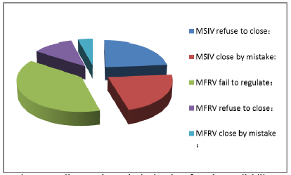
Figure 2.
Failure mode results in the plant forced unavailability
Table 7. Probabilistic availability assessment result
| PAA summary | Failure mode | Failure rate | Unit | Time(hours/year) | UU type | Shutdown overhaul time(h) | Forced shutdown overhaul time h (line) | Plant forced shutdown overhaul time (h/year) |
|---|---|---|---|---|---|---|---|---|
| VVP | refuse to close | 0.00031 | time | 12 | 3a | 62 | 0.2306 | 0.6918 |
| close by mistake | 0.0000019 | h | 7884 | 1a | 14 | 0.2097 | 0.6291 | |
| ARE | fail to regulate | 0.0000028 | h | 8760 | 1a | 17 | 0.3753 | 1.1259 |
| refuse to close | 0.0003 | time | 6 | 3a | 62 | 0.1116 | 0.3348 | |
| close by mistake | 0.000000308 | h | 8760 | 1a | 17 | 0.0402 | 0.1206 | |
| Totalamount of single reactor (h/year): | 2.902 | |||||||
The plant forced shutdown time is estimated to be 2.902 hours/year caused by failures.The disorder or degradation of the main feed-water system is less than 2 hours of initial forced unavailability distribution and meets the reliability requirements.However, the unavailability time of the main steam pipeline is more than 0.99 hoursand slightly exceeds the initial allocation requirement.It needs to be optimized.
Other critical systems of nuclear island NI are finally analyzed, including contributions these systems made to forced shutdown time of nuclear power plants to make sure that forced shutdown time caused by critical systems of nuclear island NI is less than the target value: 3 days.
6. Forced Unavailability Optimization
As for systems where the calculation results do not meet the initial forced unavailability distribution, feedback should be given to the design department for circular optimization. It can be optimized mainly through the following three aspects:
1)Equipment with long mean time between failures MTBF and high reliability should be used in design to improve equipment (especially CCM equipment) reliability of units, lower failure rate, extend mean time between failures MTBF of equipment, and reduce times of forced shutdown.
2)After equipment failure, new overhaul technology is used to reduce mean time to repair MTTR; therefore, forced shutdown timeis shortened.
3) As for critical components with high failure rate and long maintenance time, they should be optimized in the system process (like increasing redundancy designs) and forced shutdowns caused by a single failure can be changed to double or multiple failures to reduce the critical failure modes of systems and lower the forced unavailability of systems[12-13].
4) The initial forced unavailability allocation can be adjusted according to the optimization results, so that the calculation results are close to or meet the initial reliability requirements.
Based on the above calculation results, the failure of adjustment failure of the main feed-water regulating valve is the main factor that causes the forced unavailability, that is, a weak link that accounts for 38.8% of all the failure modes.According to Table 5, the high failure rate of the main isolation valve and the longer repair time are the main factors that account for the high proportion of the main isolating valve [14-15].
7. Conclusions
The forced unavailability of units not only influences economic indicators of nuclear power units like availability, but also seriously threatens the safe operation of units.It is significantly important for the safety and economy of nuclear power units to reduce forced shutdown times and shorten forced shutdown times of nuclear power units.
In this paper, based on the third generation EPR unit, the unplanned shutdown time that affects availability is calculated, critical weaknessesare found, optimization methods are put forward, and feedback is given at the design stage to continuously optimize equipment reliability of nuclear power systems and improve the unit economy under the premise of meeting safety requirements through the PAA method.This will provide not only a good reference in design, system configuration, and equipment selection of new nuclear power plants, but also reference suggestions to improve the reliability of nuclear power units.
Reference
“An Integrated Management Method to Improve the Capability Factor of Nuclear Power Plant, ”
“Advanced Nuclear Technology: Equipment Reliability for New Nuclear Plants: Industry Recommendations for Design, ”
“Calculation of Design Availability Factors for Unit 1 and 2 of Taishan Nuclear Power Plant, ”
“Optimization of Nuclear Power Station Overhaul Period, ”
EPR Taishan Nuclear Power Plant, Probability Availability Analysis PAA Guidelines
“Optimization of Overhaul Period for Nuclear Power Plant, ”
“Study on the Management of Overhaul Period in Nuclear Power Operation Company,
”
