


1. Introduction
Thermal incremental forming of magnesium alloy sheet is a kind of warm, dieless and flexible forming technology [1]. Firstly, the magnesium alloy sheet is heated to a certain temperature to make the sheet metal have good formability. Then, the three-dimensional shape is divided into a series of two-dimensional layers along the contour line using the idea of delamination. The final shape is obtained after local deformation of the sheet metal layer by layer. This technology does not need special mould. This technology helps to shorten the development period of metal sheet metal parts and saves the massive cost of mould manufacturing; it can also be applied to sample trial and multi-kind and small-quantity production. It has a broad application prospect in aviation, automobile, ship and other manufacturing industries.
However, in the process of thermal incremental forming of magnesium alloy, a phenomenon of curved convex towards the positive normal line of the machining face at the bottom surface of the formed part will occur. Under certain technological parameters, this phenomenon is very obvious, becoming one of the important reasons affecting the precision of formed parts, thus affecting the practicability of thermal incremental forming technology. Therefore, the problem of convex has attracted the attention of some Chinese and overseas scholars to carry on studies. L. D. Napoli et. al studied the phenomenon of convex and considered that the main reason for the convex is the plane stress inside the formed part, but no systematic research has been done [2]. G. Hussain et. al studied the height of convex of various materials with different properties during incremental forming process, but the influence of various technological parameters on the height of convex has not been taken into account [3]. C. Zhen et. al studied the problem of convex with the experimental method, and analyzed the influence of forming angle of parts, diameter of tool head, thickness of sheet metal et. al on the convex, but did not carry on the in-depth study to the causes of the convex [4]. X. F. Shi et. al analyzed the causes of convex phenomenon from the macroscopic view, and considered that the bottom convex was occurred by the horizontal force of tool head, but did not take into consider the effect of bending stress of sheet metal on convex [5]. Therefore, there are still many deficiencies in the research of convex phenomenon, which requires more in-depth study of the convex phenomenon and understanding of the factors that affect the size of convex that control the height of convex to improve the precision of formed parts. In this paper, the effects of forming temperature, interlayer spacing and bottom side length on the convex are studied by the method of numerical analysis and experimental verification. The causes of the convex are analyzed, which provides a theoretical basis for further reducing the convex and improving the precision of the formed part.
2. Finite Element Analysis
2.1. Material Constitutive Model
The AZ31B sheet was selected and tested by inductive coupling plasma emission spectrograph (ICP-OES) and other equipments. The component content is as shown in Table 1. The tensile test for sheet metal was carried out by means of microcomputer controlled electronic universal testing machine, and the material performance parameters were obtained, as shown in Table 2. At the same time, the tensile and compression curves of different angles were obtained.
Table 1. Experimental sheet component content
| Type | Al (%) | Zn (%) | Si (%) | Fe (%) | Mn (%) | Mg (%) |
|---|---|---|---|---|---|---|
| AZ31B | 2.5 | 0.707 | 0.146 | 0.0137 | 0.276 | Margin |
Table 2. Material performance parameters of experimental sheets at different tempera
| Temperature (℃) | Modulus of elasticity (Gpa) | Tensile strength (Mpa) | Yield strength (Mpa) | Poisson’s ratio |
|---|---|---|---|---|
| 100 | 36.1 | 222 | 144 | 0.35 |
| 150 | 26.2 | 194 | 118 | 0.38 |
| 200 | 25.0 | 159 | 101 | 0.42 |
| 250 | 23.4 | 122 | 83 | 0.45 |
Magnesium alloy has close-packed hexagonal crystal structure. Its plastic deformation exists two kinds of deformation mechanism of dislocation glide and twinning, which lead to large tension-compression asymmetry of magnesium alloy. In addition, the texture phenomenon inside extruded magnesium alloy also shows remarkable anisotropy characteristic. In order to improve the accuracy of numerical simulation, a CPB06 constitutive model, which takes into account both tension-compression asymmetry and anisotropy, is adopted to predict the process of thermal incremental forming. The yield criterion [6] is
F denotes representation yield surface size, and k as the parameter to describe the asymmetry of tension-compression of the material. α is the order of the homogeneous equation. For magnesium alloy material, α = 2 [7]. σ1, σ2, σ3 are the 3 principal values of the stress tensor. σ = C[S] is the tensor after linear variation made to Cauchy deviatoric stress tensor S, C denotes the anisotropic parameter, describing the linear transformation tensor of anisotropic yield, as shown in Formula (2).
Considering the homogeneity of the yield surface function and the characteristics of linear transformation, assume that C11=1. Because the uniaxial tension and compression tests are carried out along the in-plane, assume C44 = C55 = C66 [7]. Set up an error function as shown in Formula (3). It gives the yield stress
Table 3. Anisotropic parameters of CPB06 yield function (200℃)
| k | C11 | C12 | C13 | C22 | C23 | C33 | C44 | C55 | C66 |
|---|---|---|---|---|---|---|---|---|---|
| -0.1421 | 1 | -1.9548 | -1.0712 | -0.6471 | -1.0475 | -2.0174 | 1 | 1 | 1 |
2.2. Finite Element Modeling
In order to study the convex problem in thermal incremental forming of magnesium alloy, the finite element model was established by using ABAQUS software, and the numerical simulation of single point thermal incremental forming was carried out. The inverted cone is selected as the test model, as shown in Figure 1. The tool header is set to a discrete rigid body without deformation by default. The size of the sheet metal is 150mm×150mm, the thickness is 1.5mm, the compression area is divided at the edge of the sheet, and the degree of freedom of X and Y direction is constrained to replace the upper platen. The lower platen is placed below the sheet, which constrains all degrees of freedom and supports the edge of the sheet. As shown in Figures 2 and 3, the surface to surface contact algorithm is adopted during analysis, the tool head is the main surface, and the forming area of the workpiece is the slave surface. The feed speed of the tool head is set to 600mm/min, the motion curve is contour line, and the processing depth is 25mm, as shown in Figure 4.
Figure 1
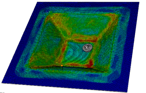
Figure 1.
Finite element analysis model
Figure 2
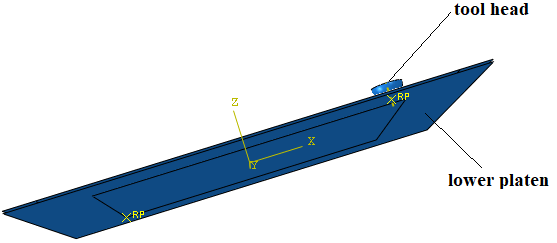
Figure 2.
Assembly of finite element model
Figure 3
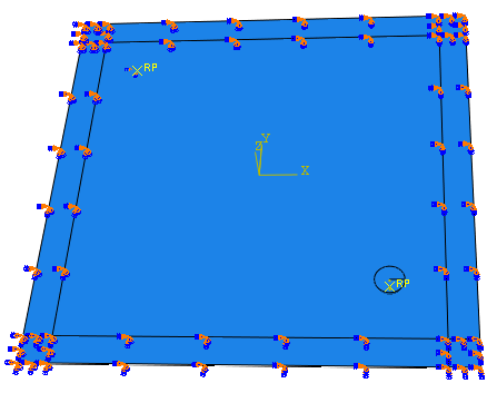
Figure 3.
Sheet metal model edge fixed
Figure 4
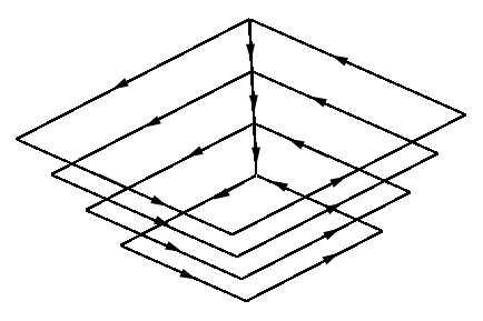
Figure 4.
Inverted cone path
2.3. Calculation of Convex
The calculation method of bottom convex is shown in Figure 5. After the forming process, two points closest to theoretical profile A(x1, z2), B(xn, zn) are found on the left and right side of the bottom surface respectively. The linear equation of AB, is shown as Formula (4), and the slope is shown as Formula (5).
Figure 5
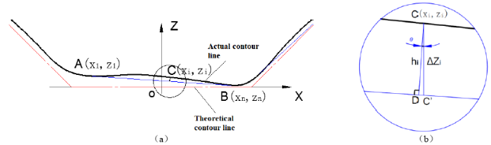
Figure 5.
Calculation method of convex
zi can be measured by substituting the C-point x coordinates into the Formula (6), then we can get $z^{'}_{i}$.
The following can be obtained from Figure 5:
The convex h is:
Formula (4), (5), and (6) are substituted into (7); the bottom surface convex value can be obtained by selecting the maximum value.
3. Numerical Analysis Results
3.1. Effect of Bottom Area on Convex
By setting the forming temperature to 200℃, forming angle to 45°, interlayer spacing to 1mm, the bottom side length 50mm, the finite element analysis is carried out. The convex analysis with processing depths of 2mm, 12mm, 17mm and 25mm is carried out. The results are shown in Figure 6. The bigger the processing depth is, the smaller the bottom convex is. This is because with the increase of the depth, the side length of the bottom surface decreases, which results in the reduction of the bending degree of the bottom surface and the reduction of the convex.
Figure 6
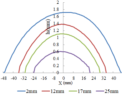
Figure 6.
Convex value of different processing depth
By setting the forming temperature to 200℃, the forming angle to 45°, the spacing between layers to 2mm, the bottom side length to 20mm, 30mm, 40mm and 50mm, finite element analysis is conducted respectively. The results are shown in Figure 7; the smaller the bottom section side length, the smaller the bottom convex value. Therefore, the convex value is proportional to the bottom side length.
Figure 7
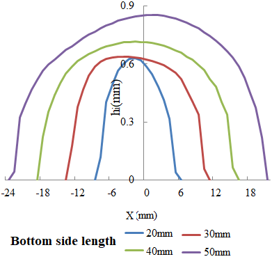
Figure 7.
Convex value of formed parts with different bottom area
3.2. Effect of Forming Temperature on Convex
By setting the forming angle to 45°, the interlayer spacing to 1mm, and the forming temperature to 100℃, 150℃, 200℃ and 250℃, the finite element analysis is carried out respectively. The convex after processing is shown in Figure 8. The lower the forming temperature, the smaller the convex. However, the study results of convex at different processing depths do not conform to this rule, as shown in the Figures 9, 10, and 11. At the initial stage, the lower the forming temperature, the bigger the convex. When processing depth reaches to 12mm, the effect of forming temperature on the convex is as same as that of the initial stage, but the value of the convex is very close. When processing depth reaches 17mm, the law of influence has changed partly. When the processing is finished, the effect of forming temperature on the convex is contrary to the that of initial stage. Therefore, the size of the convex is not only affected by the forming temperature, but also the bottom area.
Figure 8
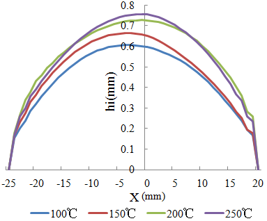
Figure 8.
Convex figure with processing depth 25mm
Figure 9
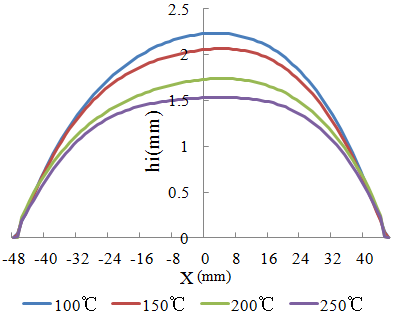
Figure 9.
Convex figure with processing depth 2mm
Figure 10
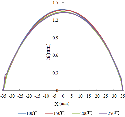
Figure 10.
Convex figure with processing depth 12mm
Figure 11
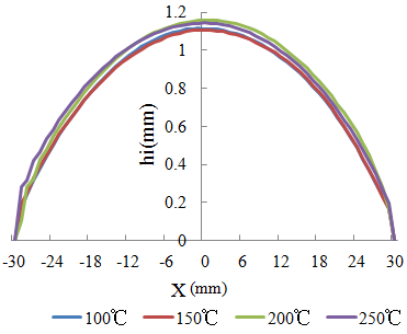
Figure 11.
Convex figure with processing depth 17mm
The forming temperature affects the height of the convex by changing the processability of the sheet metal. The magnesium alloy has a close-packing hexagonal crystal structure. Only three slip systems on the basic plane can be started at room temperature, which is far lower than the requirement of at least five independent slip systems for uniform deformation of polycrystals. With the increase of forming temperature, the non-base slip systems are activated, accompanied with dynamic recrystallization that leads to fundamental ductility transformation of the forming properties of magnesium alloys. Thus, the plastic property of magnesium alloy is enhanced and deformation resistance of magnesium alloy is reduced [8]. When the bottom area is larger, the convex of sheet metal with low forming temperature and high deformation resistance is larger. When the bottom area is small, the convex of sheet metal with high forming temperature and low deformation resistance is larger.
3.3. Effect of Interlayer Spacing on Convex
By setting the forming temperature to 200℃, the forming angle to 45°, and the interlayer spacing to 1mm, 1.5mm, 2mm, and 2.5mm, finite element analysis is carried on. Figure 12 is convex at different interlayer spacing after processing. With the increase of interlayer spacing, the bottom convex increases. Figure 13 shows the convex when processed to the second layer. It can be seen from the figure that the larger the interlayer spacing, the greater the curvature of the bottom surface and the bigger the convex after forming. Although when the interlayer spacing is large, the processing depth is larger, the side length of the bottom surface of the formed part is smaller, which affects the convex. However, since the interlayer spacing is very close, the effect of bottom side length is not enough to change the effect law of interlayer spacing on convex. Therefore, the influence of interlayer spacing on convex is mainly due to the greater curvature of the bottom surface when the interlayer spacing is larger. When the processing depth is 25mm, though the bottom area changes, the convex value decreases significantly. However, the effect law of interlayer spacing on the convex is not changed.
Figure 12
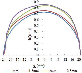
Figure 12.
Convex of different layer height after the forming process
Figure 13
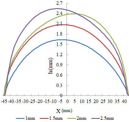
Figure 13.
Convex being processed to the second layer
4. Experimental Verification
4.1. Forming Principle
The thermal incremental forming principle of liquid medium heating is shown in Figure 14. The liquid is filled into a incremental forming device so that a sealed liquid pool is formed at the bottom, which is connected to the outside hydraulic circuit. By adjusting the overflow valve in the hydraulic circuit, the liquid can maintain a certain pressure, which plays a certain supporting role to the sheet metal. At the same time, the liquid is heated by the heating device in the sealed liquid pool, and the temperature is controlled through the control system. Before processing, the liquid is heated and the temperature gradually rises to the set value, and the temperature is kept constant through the control system. The sheet metal is heated by liquid and gradually reaches a certain equilibrium temperature. By this time, the forming tool head moves according to the predetermined track under the control of the NC program, the sheet metal is extruded layer by layer and deformed, and the deformation gradually accumulates to form the workpiece [9].
Figure 14
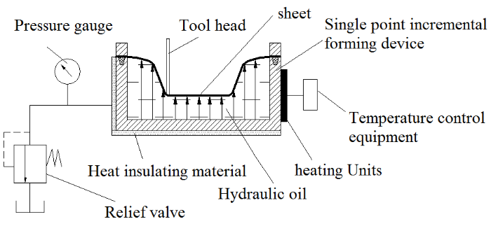
Figure 14.
Schematic diagram of experimental platform
4.2. Forming Device
The forming device is mainly composed of NC machine of CY-VMC850 machining center, single-point incremental forming device, heating plate, overflow valve, pressure gauge, insulation material, temperature control instrument, hydraulic oil and so on, as shown in Figure 15. The upper and lower blank holder is used to fix the processed sheet metal and the heating plate is used to heat the sheet metal through heating the inner hydraulic oil. The internal hydraulic oil uses No. 320 heat conductive oil, the tool head material is tungsten carbide-cobalt cemented carbide, and the hardness is 65-68 HRC.
Figure 15
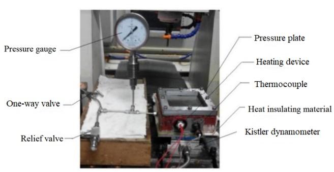
Figure 15.
The experimental platform diagram
4.3. Results of Experiments
With the above experimental device, the same parameters as the finite element analysis are set, and the single point incremental forming process is carried out. After processing, the LaserRE6003 laser scanner is used to scan the formed sheet metal. With the point cloud after scanning, model the cross section curve of the actual formed part in 3D software. By comparing and calculating the theoretical curve with the method of section 2.3, the true height of the bottom convex h is obtained. To reduce the measurement error, the steps above are repeated 10 times, taking the average as the final measurement result, as shown in Figures 16, 17, 18, and 19. The results are in agreement with the results of finite element analysis.
Figure 16
Figure 16.
Convex of formed parts with different number of machining layers
Figure 17
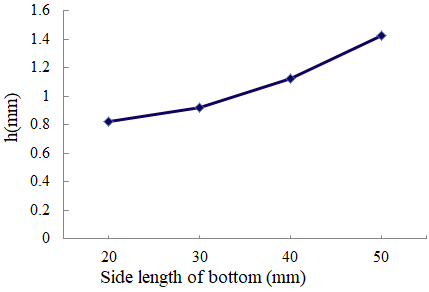
Figure 17.
Convex figure of formed parts with different side length of bottom surface
Figure 18
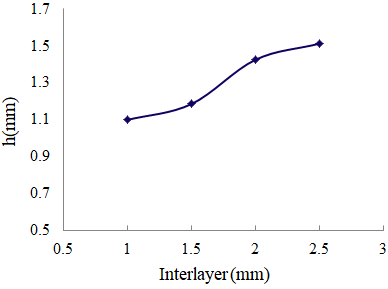
Figure 18.
The convex of formed parts with different interlayer spacing
Figure 19
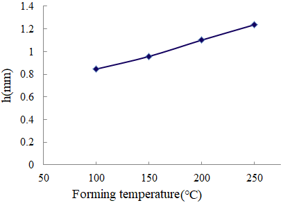
Figure 19.
The convex of formed parts with different forming temperature
It can be seen from the figures that when the opening side length is 100mm and the processing depth is 25mm, the higher forming temperature, the larger interlayer spacing and the larger bottom side length will increase the bottom convex. In the actual forming process, the shape and thickness of the workpiece are often determined, and the smaller interlayer spacing and the smaller bottom side length will reduce the convex. If the forming depth is small, the higher forming temperature will help to reduce the convex. A higher forming depth and a lower the forming temperature can reduce the convex.
5. Analysis of the Causes of Convex
From the above finite element analysis, it can be seen that the factors influencing the size of convex in thermal incremental forming of AZ31B magnesium alloy sheet metal are forming temperature, interlayer spacing, bottom side length and so on. The stress direction of the sheet metal section is shown in Figure 20. Figure 21 shows σ11, σ22, σ33 stress distribution with a forming temperature if 200℃, the forming angle 45°, the side length of the bottom section 50mm and the interlayer spacing 1mm. It can be seen from the figure that during forming processing, the upper surface of the workpiece is subjected to pressure stress and the lower surface of the workpiece is subjected to tensile stress in the vicinity of the forming tool head. Far from the area of the tool head, the upper surface of the workpiece is subjected to tensile stress, and the lower surface of the workpiece is subjected to pressure stress. The stress distribution law in three directions is basically the same. This is a kind of bending stress state. The different stress state leads to the different plastic strain of the upper and lower surface, which lengthens the upper surface of the formed part, and shortens the lower surface of the forming part, thus the phenomenon of convex occurs. Therefore, the main cause of convex phenomenon is the bending stress in sheet metal processing, which makes the upper and lower surfaces suffer the stress difference caused by different sizes of stress.
Figure 20
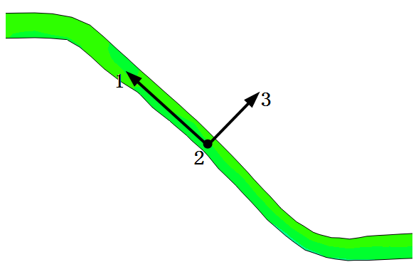
Figure 20.
Schematic diagram of stress direction of sheet metal cross section
Figure 21
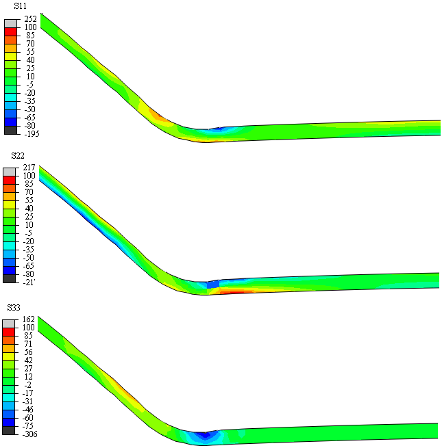
Figure 21.
σ11, σ22, σ33 stress distribution
Stress distribution of σ11、σ22、σ33 on upper and lower surfaces as shown in Figure 22, 23, and 24. Numerically, σ33 is much smaller than σ11 and σ22 during processing, so the convex is mainly caused by stress of σ11 and σ22. For the bottom surface,
Figure 21
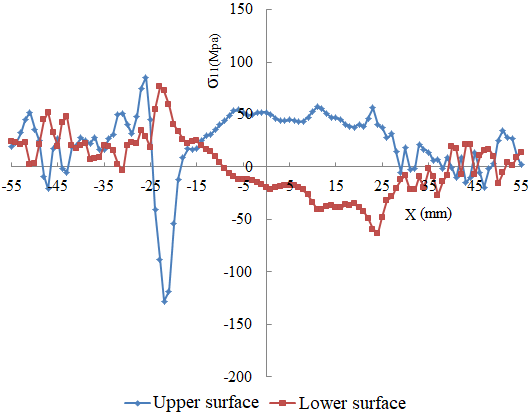
Figure 21.
σ11 stress distribution on upper and lower surfaces
Figure 23.
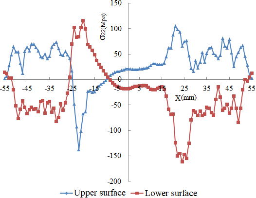
Figure 23.
σ22 stress distribution on upper and surfaces
Figure 24.
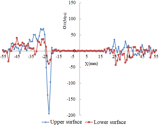
Figure 24.
σ33 stress distribution on upper and lower surfaces
Figure 25.
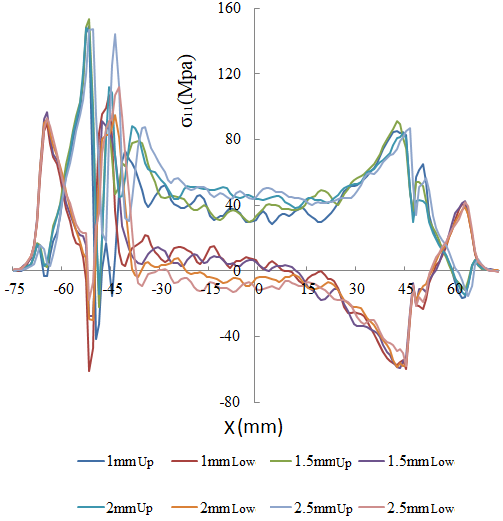
Figure 25.
σ11 figure of different interlayer spacing when processed to the first layer
The experimental results show that at the same forming temperature, the bottom side length has a significant effect on the convex, and the bottom bending can be simplified as the elastoplastic bending problem of simply supported beam. The larger the bottom side length, the larger the maximum deflection then the bigger the convex is [10]. The forming temperature affects the convex size by changing the processing performance of the material. When the processing depth is smaller, the lower the forming temperature, and the bigger the convex due to the larger side length of the bottom surface. When the processing depth is larger, the bottom side length is smaller. The higher the forming temperature, the bigger the convex. Therefore, if the processing depth of the formed parts is small, in order to reduce the convex, it is advisable to adopt a higher forming temperature. On the contrary, the bigger the depth, the lower the forming temperature can reduce the convex. Under the same forming temperature, the convex can be reduced by reducing the side length of the bottom surface. Under the condition that the forming temperature and the side length of the bottom surface are both determined, the size of the convex can be reduced by reducing the interlayer spacing.
6. Conclusion
The length of the bottom side of the formed part has a significant effect on the size of the convex. The smaller the side length of the bottom surface, the smaller the convex; otherwise, the bigger the convex.
The increase of forming temperature can change the formability of the material, but the convex value is also affected by the bottom side length. The size of the convex is the result of the comprehensive effect of the forming temperature and the bottom side length.
In the process of single point incremental forming, the bottom surface is in a typical bending stress state. When the shape and forming temperature of the formed parts are both determined, the convex is mainly caused by the stress difference ∆σ11 between the upper and lower surfaces, and the value of the convex is proportional to ∆σ11. A bigger interlayer spacing leads to a bigger ∆σ11, which results in a bigger convex value.
Acknowledgements
This work is supported by the National Natural Science Foundation of China (Grant No. 51475366, No. 50975229).
Reference
New Process Law of AZ31B Magnesium Alloy Axisymmetric Parts Single -Point Die Free Thermal Incremental Forming
,”
A Simple Approach for Reducing Profile Diverting in a Single Point Incremental Forming Process
,”
An Experimental Study on Some Formability Evaluation Methods in Negative Incremental Forming
,”
Analysis of Convex Issue in NC Incremental Forming
,”
Investigation on Error Compensatory Process of Pyramidal Parts Formed by Single Point Incremental Forming
,”
Orthotropic Yield Criterion for Hexagonal Closed Packed Metals
,”
Mechanical Properties and Constitutive Analysis of AZ31B Magnesium Alloy Extrusion Material
,”
On Magnesium Alloy Sheet Heated in Liquid Medium Hot Progressive Forming Limits
,”
Research on Thermal Incremental Forming Springback of Liquid Medium Heated Magnesium Alloy
,”
Mechanical Behavior and Microstructural Analysis of Extruded AZ31B Magnesium Alloy Processed by Backward Extrusion
,”
