


1. Introduction
Along with the urban traffic flow daily increasing, the urban bridge has also been under overload transit for a long time. There are more and more diseases of bridge structure, and the standard for subway tunnel crossing bridge has become increasingly strict. Due to the characteristics of irregular-plate bridge, including its beautiful appearance, varied forms, and wide applicability, it has been widely applied in urban overpasses [1]. As an irregular repeated ultra-static fixed point supporting plate, it is extremely sensitive about the settlement of various pier columns. Thus, the foundation settlement has a bigger influence on irregular plate, and the dangerous region of the structure is near the central pier beam, the plate edge and the support [2]. The daily increased newly built subway lines inevitably require crossing irregular-plate bridge foundation. Such foundation is generally relatively scattered, with limited safety stock; the plate thickness of the upper structure is relatively small, and mostly adopt pre-stressed structure. Different from crossing general buildings, the structural deformation permitted for crossing irregular-plate bridge foundation is stricter, and the differential settlement for foundations should be controlled within 5mm. In order to solve such engineering problems, a set of mature analysis method and reliable control measures are studied, which are imperative.
Previously, there were some applications of stratum reinforcement and pile foundation underpinning technologies in engineering of subway crossing irregular-plate bridge [3] such as Beijing Subway Line 10 crossing Guomao Bridge Irregular Plate Area. There are few theoretical researches about the effect of reinforcement measures of the irregular-plate bridge foundation’s deformation such as control measures needing to be improved. At the same time, foreign research results in this area are very few, and the impact analysis on the crossing construction is only based on numerical simulation and engineering experience. In summary, the current study is limited, and risk assessment models and methods of quantitative science has not yet formed. There is no universal system and norms for irregular-plate bridge in the design. process. This is the reason why theoretical research and practical engineering still needs to be conducted.
This paper relies on the engineering project about the interval tunnel of Beijing Subway Line 10 Phase 2 crossing irregular-plate of Xinxing Bridge, and then by virtue of finite difference method (Flac3D). It studies the control effect on the deformation of irregular-plate bridge through stratum reinforcement and pile foundation underpinning, analyze the risks of the key construction procedures and underpinning control points, and puts forward corresponding improvement measures in combination with the control effect.
2. Engineering Case Type for Crossing the Irregular-Plate Bridge and Risk Analysis
2.1. Crossing Type and Risk Analysis
Beijing Subway Line 10 is extend to the north of Xinxing Bridge from the south of Lianhua Bridge, and presents a south-north direction. The bridge has a total of 5 links, of which the second and fourth links are irregular-plate, adopting cast-in-place pre-stressed concrete. The plate thickness is 0.76m, the foundation is expansion pile of manual digging, and the single column support is irregular-plate. The positional relationship between the irregular-plate bridge and the interval tunnel is shown in Figure 1 and 2.
Figure 1
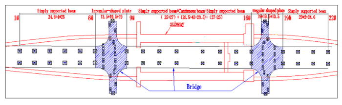
Figure 1.
General layout of irregular-plate bridge
Figure 2
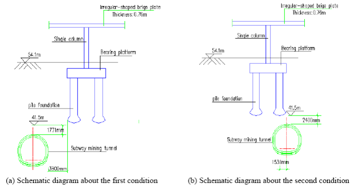
Figure 2.
Schematic diagram about the relationship between the interval tunnel and the irregular-plate bridge
The subway crossing the Xinxing Bridge has a great influence on more than 10 piers in the 6-9# and 16-19# Irregular-plate Bridge areas. The relationship between subway structure and irregular-plate bridge pile can be divided into two types, as per whether it can adopt stratum reinforcement measures. The first type is that two structures have intervals (the interval is above 3m) at the vertical space and stratum isolation reinforcement can be conducted; the second type is that two structures have no intervals (the interval is 0m) at the vertical space and the stratum reinforcement measures can’t be adopted. The entire bridge totally has 4 piers belonging to such condition. Under such condition, the construction of subway structure can cause a very big disturbance to the bottom stratum of pile foundation, and the stratum stress loss can make the pile foundation lose its bearing capacity. Through the calculation of the original bridge design company, during the subway construction process, the permissible settlement value for the foundation of irregular plate shall not exceed 3mm (the differential settlement for the adjacent foundations shall not exceed 2mm), and the foundation shall not have any upward displacement. Through scheme comparison, it is held that: the first type of underneath crossing conditions should adopt the stratum isolation scheme, the second type of underneath crossing conditions should adopt the scheme about the complete underpinning of pile foundation, i.e., building two new piles at the two sides of the underpinning bearing platform to active underpin the originally old piles. The newly building steel beam concrete bearing platform connects the underpinning pile and the old bearing platform to improve the bearing capacity of the pile foundation, and ensure that the foundation settlement during the subway crossing process shall not exceed the control standard; refer to Figure 2 for Sectional view of Pile Foundation Underpinning.
Figure 3
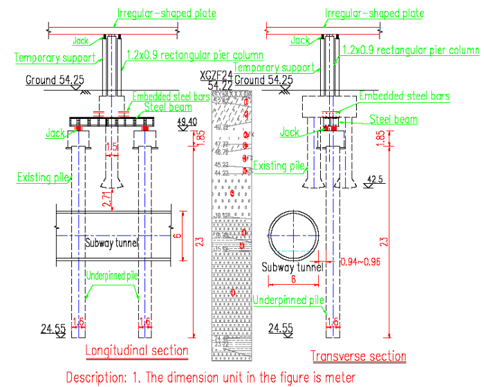
Figure 3.
Sectional view of pile foundation underpinning
As per the construction sequence, the influence of main working procedures on the bridge pier is analyzed. The working procedures are as follows: Working Procedure 1 is the construction preparation, Working Procedure 2 is excavating the pile hole after constructing the composite anchor pile to isolate the ground, Working Procedure 3 is the excavation of new bearing platform, Working Procedure 4 is finished steel bearing platform, Working Procedure 5 is girder lifting, and jack arrangement, Working Procedure 6 is loading the jacking force to the top lifting force, Working Procedure 7 is the cutting of original pile, Working Procedure 8 is the solidification of underpinned pile and the new bearing platform, Working Procedure 9 is the excavation of subway structure. Working Procedure 2 and 9 have relatively big influence on the bearing capacity of pile foundation. This paper adopts FLAC to conduct special value analysis on Working Procedure 2 and 9, and conduct load experiment and design calculation comparison for Working Procedure 6.
Since the eastern and western side plates for the irregular-plate of Xinxing Bridge are symmetric, the analysis of the western side plate is adopted. The model dimension is 67.15m×34m×60m, the design load of the bridge is 10.7 kPa, and the point of application is on the bridge floor; refer to Figure 4 for the model.
Figure 4
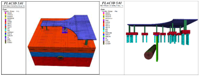
Figure 4.
Calculation model
2.2. Design Scheme and Calculation Parameters
As for the Key Working Procedure 2, as per two working conditions (Working Condition 1 adopts non-reinforced stratum, and Working Condition 2 adopts reinforced stratum) is analyzed; as for the Key Working Procedure 9, as per three working conditions (Working Condition 1 adopts conventional stratum reinforcement; Working Condition 2 conducts subway crossing after adopting pile foundation underpinning, and stratum isolation; Working Condition 3 adopts pile foundation underpinning, stratum isolation and reinforcement) and stress relief is analyzed. Refer to Table 1 for material parameters.
Table 1. Main material parameter table
| Name | E/MPa | μ | ρ/kg | C/kPa | φ/° | Noumenal Structural |
|---|---|---|---|---|---|---|
| C30 concrete | 3×10⁴ | 0.2 | 2500 | / | / | Elastic |
| C50 concrete | 3.45×10⁴ | 0.2 | 2500 | / | / | Elastic |
| Floury soil | 10 | 0.24 | 1840 | 10 | 8 | Mohr-Coulomb |
| Gravel | 20 | 0.31 | 2010 | 24 | 20 | Mohr-Coulomb |
| Mudstone | 73 | 0.36 | 2250 | 20 | 50 | Mohr-Coulomb |
The model includes irregular-plate, bridge pier, bearing platform, pile foundation, stratum, tunnel and duct piece. The thickness for irregular plate is 0.76m, the dimension of bridge pier is 0.9m×1.2m×7.45m, the dimension of bearing platform is 6.5m×3m×2.5m, the diameter and length of original pile is 0.6m×7.9m, the diameter and length of the new pile is 0.8m×25m and the dimension of the bearer is 1.8m×10.1m×1.05m.
2.3. Displacement Characteristics in the Excavation Process of Underpinned Pile
In order to know the influence of excavating new pile hole on the displacement of the original bearing platform, the horizontal displacement (x) monitoring points for the symmetry points at the two sides of the pile hole are set specific to two working conditions of possessing no measures and possessing stratum reinforcement measures (improve the elasticity modulus of soil by 3 times) [4-7]; it will be monitored every 5m along the depth. Meanwhile, it will also monitor the horizontal displacement (x) and vertical displacement (z) for the pile block near the original pile as well as the settlement of each bridge pier; as for the monitoring point layout diagram, please refer to Figure 5.
Figure 5
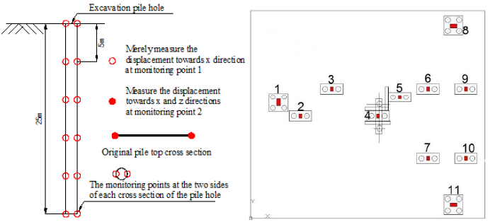
Figure 5.
Monitoring point layout diagram
Table 2. Settlement of various pier columns without reinforcement measures
| Pile column No. | Pile column settlement without reinforcement measures/mm | Pile column settlement with reinforcement measures/mm |
|---|---|---|
| 1 | -0.56 | -0.12 |
| 2 | -0.55 | -0.11 |
| 3 | -0.58 | -0.13 |
| 4 | -0.92 | -0.32 |
| 5 | -0.61 | -0.14 |
| 6 | -0.59 | -0.07 |
| 7 | -0.59 | -0.09 |
| 8 | -0.55 | -0.11 |
| 9 | -0.60 | -0.13 |
| 10 | -0.59 | -0.11 |
| 11 | -0.55 | -0.09 |
Figure 6
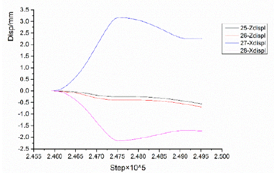
Figure 6.
Chart about the original displacement of pile block before reinforcement excavation
Figure 7
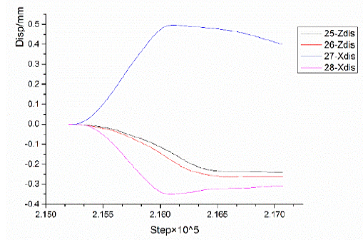
Figure 7.
Chart about the original displacement of pile block before reinforcement excavation
As seen from Figure 5 and Figure 6, under the condition of no reinforcement, the displacement of the original pile block can reach to 3.2mm along x direction. The left-side original pile block has displacement towards the right, while the right-side has displacement towards the left, i.e., there are displacements towards the excavation hole. Meanwhile, the pile block has partial displacements towards the downward direction, which is about -2.1mm. Under the condition of stratum reinforcement measures, the displacement of the original pile block towards x direction is very small, which is about 0.48mm. There are displacements at the two sides towards the excavation hole. The pile block is also generating a tiny displacement towards the downward direction, which is about -0.32mm, simultaneously.
As seen from Table 2, under the condition of no reinforcement, the settlement value of -0.55 (No. 2, 8 and 11 pier columns) is the smallest, and can reach to -0.55m. The maximum settlement for No. 4 pier column can reach to -0.92m. Under the condition of reinforcement, the minimum settlement value for No. 7 and 11 per columns can reach to -0.09m, and the maximum settlement value for No. 4 pier columns is -0.32m. The settlement value of pier columns is largely decreased, and the maximum decreasing amplitude reaches to 85%.
Through the aforementioned analysis, it can be seen that, after the excavation of new pile holes, the surrounding stratums of the hole will have displacement towards the hole. Under the influence of excavation, the nearby original piles will also generate tiny displacement towards the hole excavation direction and the downward direction. With the distance of the pile hole becoming bigger, the settlement of the pile column will become smaller.
2.4. Deformation Analysis on the Excavation of Subway Structure
In order to analyze the influence of various working conditions about the excavation of tunnel on the deformation of irregular-plate bridge, this paper adopts three different working conditions: Working Condition 1 adopts conventional stratum reinforcement, Working Condition 2 conducts subway crossing after adopting pile foundation underpinning and stratum isolation, Working Condition 3 adopts pile foundation underpinning, stratum isolation, stratum reinforcement, and after completing the excavation of different working conditions. Refer to Table 3 for the settlement of various pier columns, and Table 4 for the final settlement of various pier columns.
Table 3. Settlement value of pier column under various working conditions
| Pile column No. | Working Condition 1 pier column settlement/mm | Working Condition 2 pier column settlement/mm | Working Condition 3 pier column settlement/mm |
|---|---|---|---|
| 1 | -8.37 | -2.79 | -0.64 |
| 2 | -8.40 | -2.79 | -0.64 |
| 3 | -8.75 | -3.19 | -0.71 |
| 4 | -9.37 | -2.67 | -0.61 |
| 5 | -8.70 | -3.73 | -0.80 |
| 6 | -8.45 | -2.46 | -0.68 |
| 7 | -8.37 | -2.43 | -0.68 |
| 8 | -8.40 | -2.34 | -0.67 |
| 9 | -8.35 | -2.37 | -0.67 |
| 10 | -8.28 | -2.32 | -0.65 |
| 11 | -8.25 | -2.27 | -0.64 |
Table 4. Final settlement value of various pier columns
| Pile Column No. | Settlement of Various Pier Columns after the Excavation of Underpinned Pile/mm | Settlement of Various Pier Columns after the Excavation of Tunnel/mm | Final Settlement/mm | Settlement Limit Value/mm |
|---|---|---|---|---|
| 1 | -0.12 | -0.64 | -0.76 | 3mm |
| 2 | -0.11 | -0.64 | -0.75 | |
| 3 | -0.13 | -0.71 | -0.84 | |
| 4 | -0.32 | -0.61 | -0.93 | |
| 5 | -0.14 | -0.80 | -0.94 | |
| 6 | -0.07 | -0.68 | -0.75 | |
| 7 | -0.09 | -0.68 | -0.77 | |
| 8 | -0.11 | -0.67 | -0.78 | |
| 9 | -0.13 | -0.67 | -0.80 | |
| 10 | -0.11 | -0.65 | -0.76 | |
| 11 | -0.09 | -0.64 | -0.74 |
As from Table 3, under Working Condition 1, the settlement value of pier column is the biggest, of which the maximum value is -9.24mm, and the minimum value is 8.25mm. Under Working Condition 3, the settlement of pier column is the smallest, of which the minimum value is -0.64mm, and the maximum value is -0.80mm.
As seen from Table 4, Working Condition 3 adopts pile foundation underpinning, stratum isolation, and stratum reinforcement measures during the excavation period of underpinned pile and the tunnel excavation period. This can validly decrease and control the settlement of various pier columns; the final settlement value for various pier columns is 3mm smaller than the settlement limit.
To sum up, when adopting conventional strum reinforcement, the settlement for various pier columns is relatively big, and the maximum value can reach to 9.24mm. Through adopting pile foundation underpinning and stratum reinforcement, the settlement of pier and abutment is decreased, and the maximum value of settlement is merely -0.80mm. Compared with Working Condition 1, the decreasing amplitude reaches to 91%. The construction process adopts stratum isolation, reinforcement and pile foundation underpinning measures, to ensure that the bridge structure of irregular plate is safe. During the underpinning excavation period and the tunnel excavation period, it can validly decrease and control the settlement of various pier columns; the final settlement value for various pier columns is 3mm smaller than the settlement limit.
3. Active Underpinning Technology and its Control Points
The results of numerical analysis are reasonable, but it is very difficult to achieve this goal in civil engineering. It is necessary to control the reinforced concrete with high precision by means of machinery, and choose a conversion system that is easy to monitor and control the force and deformation. The structure has become the preferred carrier medium for this project because of its high precision, relatively accurate calculation of force and relatively simple mechanical properties. In the process of establishing the model, the calculation method of the vertical stiffness of the pile foundation and the rigidity of the underlying beam is obtained through programming. The method of calculating the model of the underpinning structure is established [8-10]. Combined with site conditions, a 10.1m×1.8m×1.0m steel box girder to replace the original concrete cap is designed. The steel plate changing beam is a single-box double-chamber structure. The longitudinal and cross-sections are shown in Figure 8.
Figure 8
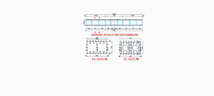
Figure 8.
Longitudinal and cross-sectional view of the steel plate changing beam
Realizing the underpinning of structural bearing capacity requires a judgment standard. The following is a simplified diagram of the deformation of the simplified supporting beam in the mid-span. The design needs to calculate the original bearing load when the load is transferred to the new supporting pile, the deformation value and stress value of the beam span. The design unit adopts MIDAS software modeling and calculation, and proposes the design judgment standard of the completion of the underpinning: when the relative displacement of the jack and the supporting beam span reaches 7.1mm (theoretical value), and the relative displacement and the jack elevation are stable, the topping force is stopped. According to the stress monitoring data and the pre-clamping force, it is determined whether or not the underpinning is completed, as shown in Figure 9.
Figure 9
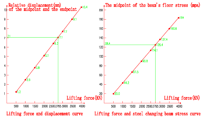
Figure 9.
Top force and displacement/steel plate beam stress curve
In order to realize 100% complete underpinning of point support pre-stress irregular plate single pier pile foundation through using active underpinning technology, the load and deformation must be controlled actively in the construction process, so that the theoretical calculation values of lifting force, displacement and stress of underpinning Jack are in good agreement with the measured values, and the three values are mutually verified, so that the underpinning can achieve higher accuracy. The key points are as follows.
1) Stress monitoring: During the pre-jacking and official jacking process, the detecting instrument to monitor the jacking force of the jack and the mid-span stress of the girder is adopted to ensure the safety of the jacking process. In the hydraulic jacking process, observe the changing conditions about the new pile foundation and the underpinning girder at any time. In case of any abnormal conditions, the process is requested to timely find out the reasons, and adopt corresponding measures.
2) Displacement monitoring: At the section position of the jack, each hydraulic jacking position is set with one observation point to monitor the displacement of each level of jacking girder.
4. Control Result of Underpinning Construction and Deformation Monitoring
4.1. Underpinning Construction Control Result
The control data during four underpinning construction processes through one-year construction monitoring is shown in Table 5.
Table 5. Control parameters during the underpinning construction process
| Underpinned pier column No. | Jacking force/kN | Mid-span relative displacement of the girder/mm | Mid-span stress/MPa | |
|---|---|---|---|---|
| 17-3 (2010.10.7) | South | 2333 | 6.0 | / |
| North | 2357 | |||
| 17-10 (2011.01.10) | South | 2525 | 6.2 | / |
| North | 2522 | |||
| 8-3 (2011.11.9) | South | 2903 | 5.6 | 97.72 |
| North | 2454 | |||
| 8-10 (2011.11.15) | South | 2666 | 5.9 | 117.11 |
| North | 2719 | |||
Refer to Figure 10 for the longitudinal line chart of girder after underpinning girder jacking of 8-3 axles. It can be seen that the displacement is well controlled during the jacking process, the displacement for the symmetry points at the two sides of the girder can be basically kept consistent, the maximum displacement for the final jacking point is respectively 10.49mm and 10.86mm, the mid-span displacement is 5.26mm, and the relative displacement between the jacking point and the mid-span is about 5.6mm.
Figure 10
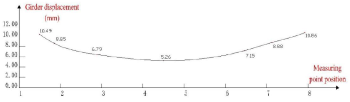
Figure 10.
Longitudinal line chart of girder after underpinning girder jacking of 8-3 axles
Refer to Figure 11 for the longitudinal line chart of girder after underpinning girder jacking of 8-10 axles. It can be seen that the displacement is well controlled during the jacking process, the displacement for the symmetry points at the two sides of the girder can be basically kept consistent, the maximum displacement for the final jacking point is respectively 9.87mm and 9.73mm, the mid-span displacement is 3.89mm, and the relative displacement between the jacking point and the mid-span is about 5.9mm.
Figure 11
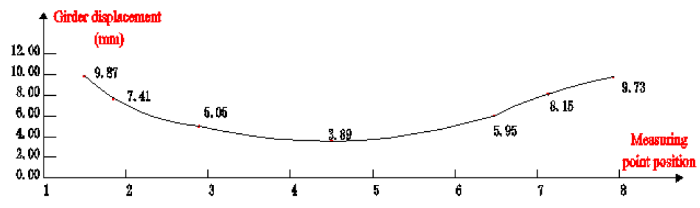
Figure 11.
Longitudinal line chart of girder after underpinning girder jacking of 8-10 axles
4.2. Deformation Monitoring Result about the Pier Columns
Figure 12
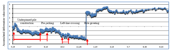
Figure 12.
Settlement time interval curve chart for 17-3# pier column
Figure 13
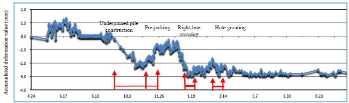
Figure 13.
Settlement time interval curve chart for 17-10# pier column
Figure 14
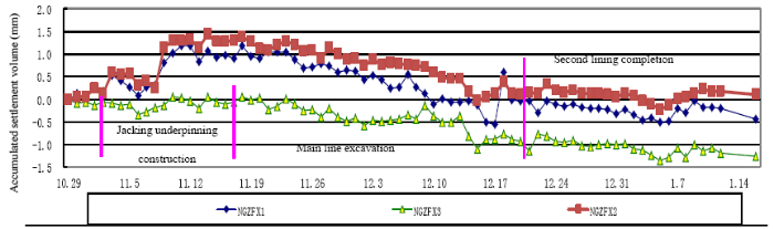
Figure 14.
Settlement time interval curve chart for 8-3# pier column
Figure 15
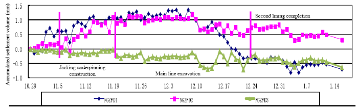
Figure 15.
The ROC curves of NB, C4.5, LR, and RF with the top 15 features
Table 6. Final settlement value of irregular-plate pier columns
| Pier No. | Final settlement/mm | Pier No. | Final settlement/mm |
|---|---|---|---|
| 17-1# | -1.3 | 8-1# | 0.1 |
| 17-2# | 0.5 | 8-2# | -1.7 |
| 17-3# | +3.5 | 8-3# | -1.3 |
| 17-4# | 0.6 | 8-4# | -2.5 |
| 17-5# | -0.6 | 8-5# | -4.8 |
| 17-6# | -0.3 | 8-6# | -3.5 |
| 17-7# | -0.3 | 8-7# | -1.0 |
| 17-8# | 0.4 | 8-8# | -0.4 |
| 17-9# | -0.8 | 8-9# | -0.4 |
| 17-10# | -2.6 | 8-10# | 0.4 |
| 17-11# | -0.4 | 8-11# | -0.3 |
The monitoring results of 17-3# and 17-10# piers settlement are shown in Figure 12 and 13. As seen from Figure 12, we know about the settlement conditions about 17-3# pier columns for the north irregular-plate bridge of Xinxing Bridge during the construction of underpinned pile, pre-jacking, and shield tunnel crossing process. We also know that the accumulated deformation value is +3.5mm. The cause of the result is that the shield construction passed through the bridge pile during the period of no consolidation of the underpinning system. After the settlement of the bridge pile becomes too large, the stratum is compensated by grouting with a large pressure in the shield tunnel, causing the pier to be lifted by 6 mm. As seen from Figure 13, we can know about the settlement of 17-10# pier columns for the north irregular-plate bridge of Xinxing Bridge during the construction of underpinned pile, pre-jacking, consolidation underpinning system and shield tunnel crossing process. We also know the accumulated deformation value is -2.6mm; the result is in line with the design requirements.
The monitoring results of 8-3# and 8-10# bridge piers settlement is as shown in Figure 14 and 15. The construction of composite anchor piles to isolate the ground, the top of the lifting platform, the underpinning of existing bridge piles, consolidation underpinning system and ensuring that the left and right lines can be excavated for crossing were all documented. The accumulated settlement value of the pier are -1.3mm and 0.4mm; the result is in line with the design requirements.
5. Conclusions
During the excavation process of underpinned pile, the surrounding stratums of the hole have displacement towards the hole. Under the condition of no reinforcement, the displacement of the original pile block towards x direction reaches to 3.2mm. Under the condition of stratum reinforcement measures, the displacement of the original pile block towards x direction is decreased to 0.48mm. Under the condition of reinforcement, the settlement value of the pier column is largely decreased when being compared with that under the condition of no reinforcement, and the maximum amplitude reduction value reaches to 85%.
During tunnel excavation, the settlement of each pier is larger when the conventional stratum is used; the maximum value reaches 9.24mm. The pile foundation underpinning, stratum isolation and stratum reinforcement can effectively reduce the settlement of the Pier; the maximum settlement is 0.80mm. Compared with working condition 1, the decline was 91%. The construction process adopts stratum isolation, reinforcement and pile foundation underpinning measures to ensure the safety of the irregular-plate bridge structure. In the new underpinning pile excavation stage and the tunnel excavation stage, the sinking of each pier can be effectively reduced and controlled. Each final settlement value of the pier column is much smaller than the settlement limit of 3 mm.
Through the risk analysis of the main processes, if the stratum reinforcement technology is used alone in the excavation of a subway tunnel crossing irregular-plate bridge, it is very difficult to control the settlement of the irregular-plate bridge pier column within 3 mm, especially the pier near the center of the settlement area has very high requirements for stratum reinforcement. In the current level of stratum reinforcement technology, the design of the pre-underpin pile foundation and the post-excavation subway tunnel is more safe.
Bridge pile foundation underpinning is a construction project with high technical content and high risk, especially for the pre-stressed plate structure with point support, the differential settlement of adjacent pile foundation needs to be controlled within 3mm. In order to meet this requirement, construction must adopt high-precision technology, and the steel underpinning girder with displacement and stress as control means can achieve this.
The control results of the four bridge piles underpinning are different. The first (17-3#) is earlier. The scheme and construction management are lacking; its result is not very satisfactory. The subsequent three bridge pile underpinning constructions are summarized in the previous technical optimization and management, and the construction results are very controllable, which is in line with the design requirements. It can be seen that the bridge pile underpinning is a precision construction task; at the same time, advanced technology and construction management are equally important.
Acknowledgements
This work was partly financially supported through Scientific research project of Beijing Rail Transit Construction Management Co., Ltd. (Metro Line ten (two) technical words No. 2013A173).
Reference
Seismic Source Effects on the Vulnerability of an Irregular Isolated Bridge
,”
The Study on Bore Piles Foundation of the Reinforced Concrete Arch Bridge Beams of Tukad Pekerisan and Tukad Penet
,”
Cyclic Response of RC Continuous Span Bridges with Irregular Configuration in Longitudinal Direction
,”
Defining a Horizontal Displacement of a Drilled Pile Foundation Using the i. a. Simvulidi Approach
,”
Punching of Flat Slabs Supported on Rectangular Columns
,”
Behavior of Pile Subject to Excavation-Induced Soil Movement
,”
The Response of Surface Structures to Tunnel Construction
,” in
Construction of Deep Foundation Ditch under a Reconstructed Multi-Storey Building on the Main Avenue of st. Petersburg
,”
Internal Force Analysis of Underpinning Structure at Adverse Construction Stage in Complex Moving Engineering
,”
Nondestructive Testing for Design Verification of Boston's Central Artery Underpinning Frames and Connections
,”
