


1. Introduction
With the development of the MHD generator, domestic and foreign scholars have found that the detonation of high-energy explosives in the combustion chamber can form plasma, and the gas has good conductivity. In the 1960s, an MHD company [1] in the United States developed a magnetic fluid generator: when the external magnetic field is 2.8T, adding some ionizing seeds to the C4 type composite, the maximum current of the device can reach 260kA. Choudhary [2] studied the conductivity of the detonation products of RDX/TNT explosive, and its maximum conductivity is 2500S/m. Beijing Institute of Technology [3] measured the maximum conductivity of TNT as1800S/m. It can be seen that the powder gas in the high temperature environment will ionize and form plasma.
The flow field of the high speed conducting gas will form the Lorenz force in the magnetic field, and the force field can change the flow state of the gas, suppress turbulence, and thus affect the heat transfer characteristics [4-5]. Bityurin’s [6] experimental results show that the hypersonic flow plasma can reduce the heat flux at the stagnation point in magnetic field, and a stable magnetic field will suppress the turbulent convective heat transfer ability and reduce the convective heat transfer capacity of conductive fluid. Dietiker [7] used the modified algebraic turbulence model to simulate plasma flow around a bluff body under the action of a magnetic field, and the calculated results show that the surface friction coefficient and heat transfer capacity can be reduced. Huang [8] provided a numerical simulation of the effect of low temperature plasma on heat transfer of aero engine tail nozzle. The results show that plasma under the control of a magnetic field can suppress the increase in temperature of the nozzle wall.
The working environment of weapon tubes is extremely bad; high temperature propellant gas lifts the wall temperature of the tube within a short time, breaking the thermal balance of the tube wall and leading to thermal softening of the surface [9]. At the same time, the mechanical friction between the projectile and the inner wall of the tube is also aggravated by the thermal softening of the metal, and the ablation of the tube produced by the high temperature propellant gas has become an important factor to reduce the service life of the weapon [10-11]. According to the analysis of the magnetic field on the heat transfer characteristics of conductive gas, a method to reduce the ablation of high temperature gas to the tube by using the magnetic field controlled plasma is presented, which aims at improving the heat resistance of the tube and prolonging the service life.
2. Turbulent Dissipation Model of Conducting Gas in Cylinder
Turbulence is a fluid flow state. When the flow rate is lower, the fluid stratifies flow, known as laminar flow. When the flow rate increases, the flow gradually forms in disorder, resulting in irregular turbulent flow. The momentum between the micro fluid mass and heat transfer rate are much higher than those of laminar flow [12]. Therefore, turbulence is an important factor to enhance the heat transfer capacity. In this paper, the turbulent dissipation model of conducting gas in a cylinder is constructed by using the method of magnetic fluid description. The effects of different magnetic fields on the flow and heat transfer characteristics of high temperature conducting gas are studied.
2.1. Physical Model
As shown in Figure 1, the gun tube is simplified into a cylindrical structure, and the conductive gas at the entrance of the muzzle velocity is U. The uniform magnetic field B is applied along the y and z directions of the cylinder.
Figure 1
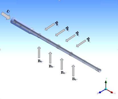
Figure 1.
Diagram of physicalmodel
According to the research object of this paper, the following basic assumptions are put forward:
$\cdot$ The flow of conductive gas in the cylinder is in the continuous medium region, and it can be studied by using the magnetic fluid dynamics method.
$\cdot$ The conductivity of the conducting gas in the cylinder is assumed to be constant.
$\cdot$ The high temperature conducting gas produced by combustion is in the local thermal equilibrium state, which satisfies the ideal gas state equation.
$\cdot$ The chemical reaction in the process of plasma flow is not considered.
2.2. Governing Equation
In the electromagnetic field, the Lorenz force in the movement of the conductive gas can be expressed as follows:
In this formula: B is the magnetic induction intensityand J is the induced current density.To meet Ohm’s law:
In the formula, the conductivity is σ, the electric field intensity is E, and the velocity of flow is U. It is known that the induction current density should be calculated firstly.
According to the Maxwell equations:
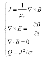
μm is the magnetic permeability, and Q is the joule heat. When the magnetic induction intensity of B is known, the Lorenz force and Joule heat can be calculated.
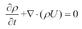
Magnetic fluid dynamics are based on non-conducting fluid mechanics [13]. Add the Lorenz force and joule heat to the momentum and energy conservation equation, and make corresponding amendments to the equations of fluid mechanics. The mass conservation equation does not involve the effects of force. Therefore, the mass conservation equation of MHD is the same as that of traditional fluid mechanics.
Mass conservation equation:
Momentum conservation equation:
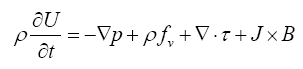
In the formula, P is the pressure, fv is other body force in addition to the magnetic force, τ is the shear stress tensor, and J×B is the Lorenz force.
Energy conservation equation:
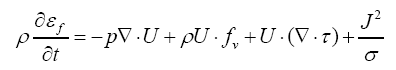
In (6), εf is the gas energy, the right end of the first term is the pressure work, the second is the volume force work, and the third is the viscous force work. Because of the magnetic fluid effect, joule heat is added to the ordinary fluid energy equation.
To simulate the effect of magnetic field on the turbulent flow, we need to consider the influence of the magnetic field in the turbulent model. This paper adopts a realizable k-ε turbulence model.
Turbulent kinetic energy equation:
In the type: k and ε respectively represent the turbulent kinetic energy and dissipation rate; $\mu $is the mixture viscosity; ${{\mu }_{i}}$is the turbulent viscosity; ${{G}_{k}}$ is the turbulent kinetic energy caused by the velocity gradient; ${{\sigma }_{k}}$ is the turbulent prandtl coefficient based on k, take σk; $\varepsilon _{em}^{k}$ is the response to electromagnetic effects of turbulent kinetic energy, $\varepsilon _{em}^{k}={{C}_{1}}\frac{\sigma }{\rho }{{B}^{2}}k$, take C1 = 0.5.
Turbulent energy dissipation rate equation:
σε is the turbulent Prandtl coefficient. Take σε=1.3,C2 =1.5,C3 = 1.9, $\varepsilon _{em}^{k}={{C}_{1}}\frac{\sigma }{\rho }{{B}^{2}}k$, and C4=1.
2.3. Boundary Conditions
Set the initial velocity of the conducting gas at the inlet of the cylinder, U=1000m/s, T=3000K, and the conductivity of $\sigma $=500S/m. The wall material is made of non-magnetic steel, and the permeability is 1.26 ×10⁻⁶H/m. The outlet is pressure exit condition,P=101325Pa,and the applied magnetic field is a uniform magnetic field. The amount of heat transfer when the gas passes through the wall is derived from the one-dimensional heat transfer formula:
In the formula, ${{\lambda }_{w}}$ is wall thermal conductivity; ${{T}_{0}}$ is the normal temperature 283.15K; and $\delta $ is the wall thickness, take $\delta =40\text{mm}$.
3. Simulation Analysis of Flow and Heat Transfer Characteristics of Conducting Gas
3.1. Model Verification
According to the MHD model mentioned above, the FLUENT software is developed by UDF. The Lorentz force and Joule heat are addedinto the momentum equation and the energy equation in the form of the source term.
Figure 2 shows the velocity distribution on the center line of the cylinder when the magnetic field of different intensity is applied along the z axis. It can be seen from Figure 2 that the velocity at the outlet of the cylinder tends to decrease as the magnetic field increases. This is because the charged particles in the conductive gas are rotated by the Lorentz force, and the applied magnetic field has a certain blocking effect on the flow of the conductive gas. The Lorentz force on the conductive gas increases, so the velocity of flow decreases more. The calculated results are consistent with the trend of velocity distribution on the center line of plasma jet under the action of magnetic field in reference [14], which verifies the reliability of the model.
Figure 2
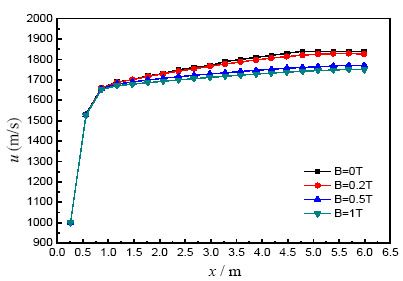
Figure 2.
Velocity curve of center line under different magnetic field intensity
3.2. Effect of Vertical Magnetic Field on the Flow Characteristics of Conductive Gas
Because of the conductivity of plasma, when it moves in a vertical magnetic field, it will cut the magnetic line to form inductive current J. The interaction of inductive current and magnetic field produces a Lorentz force in the opposite direction of motion in the plasma [15]. Figure 3 shows a schematic diagram of the plasma force. The direction of the induced current is perpendicular to the direction of the magnetic field and velocity.
Figure 3
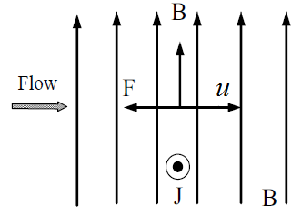
Figure 3.
Force diagram of plasma under vertical magnetic field
Figure 4 shows the vector distribution of the induced current at the exit section after a 0.5T vertical magnetic field is applied along the z axis. According to the left-handed rule, the inductive current is generated in the vertical magnetic field and the closed loop is formed through the conducting wall. Therefore, at the same cross section, the induced current and Lorentz force along the y axis are larger, andthe distribution has the characteristics of anisotropy.
Figure 4
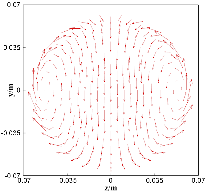
Figure 4.
Distribution of inductive current
Figure 5 shows the distribution of the turbulent kinetic energy of the conducting gas at the exit section of the cylinder without applying an external magnetic field. Figure 6 and Figure 7 show the 0.5T magnetic field applied in different directions. As shown below, without a magnetic field, the turbulent kinetic energy in the yoz section is symmetric, and it gradually increases from the inside to the outside. The external magnetic field, the charged ion of conductive gas constraints by the Lorenz force, changes from irregular thermal motion to spiral motion around the magnetic field lines. This movement can reduce the particle collision probability parallel to the field direction, thereby reducing the particle kinetic energy exchange efficiency. Its distribution has the characteristics of anisotropy in macro performance.
Figure 5
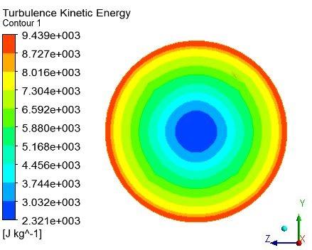
Figure 5.
Turbulent kinetic energy without magnetic field
Figure 6
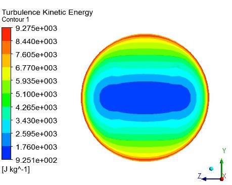
Figure 6.
Turbulent kinetic energy undermagnetic field applied along the z axis
Figure 7
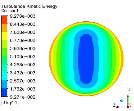
Figure 7.
Turbulent kinetic energy undermagnetic field applied along the y axis
Comparing Figure 6 and Figure 7, the turbulent kinetic energy along the magnetic field direction remains in a low level state at the center. The rapid decrease in velocity at the junction on the wall leads to a sudden increase in turbulence intensity near the boundary of wall. In the direction perpendicular to the magnetic field, the turbulence kinetic energy of conducting gas increases steadily as the distance to the wall decreases. Therefore, the turbulent kinetic energy along the magnetic field direction is significantly less than the turbulent kinetic energy perpendicular to the magnetic field.
Eddy viscosity reflects the internal friction between molecules. From Figure 8, where there is an absence of magnetic field, the maximum eddy viscosity is at the center of the exit section: it is 0.337Pa·s. After the external magnetic field, the charged particle spirals around the magnetic field line under the action of the Lorentz force, thereby reducing the particle collision probability parallel to the field direction. From Figure 9 and Figure 10, it can be seen that the magnetic field reduces the eddy viscosity. On both sides of the vertical magnetic field, the eddy viscosity is larger, and the maximum value is 0.259Pa·s.
Figure 8
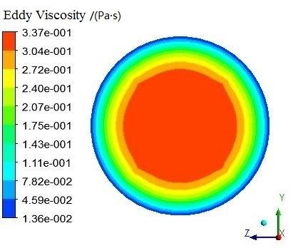
Figure 8.
Eddy viscosity without magnetic field
Figure 9
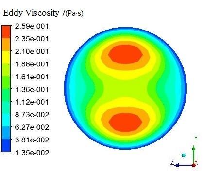
Figure 9.
Eddy viscosity under magnetic field applied along the z axis
Figure 10
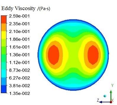
Figure 10.
Eddy viscosity under magnetic field applied along the y axis
3.3. Effect of Vertical Magnetic Field on the Heat Transfer Characteristics of Conducting Gas
Figure 11 shows the effect of different magnetic field intensities on the wall heat flux q. It can be seen that with an increase in magnetic field intensity, the heat flux density of conductive gas to the wall decreases obviously. This is because the magnetic field can suppress the turbulence intensity of the conducting gas, which results in a decrease in the turbulent kinetic energy near the wall boundary layer. The heat transfer coefficient decreases between gas and wall surface, eventually leading to an decreasein the heat flux.
Figure 11
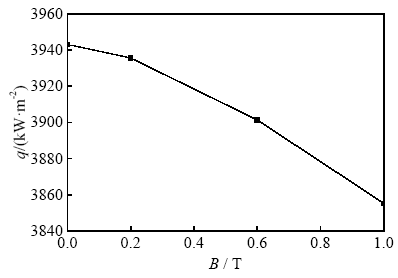
Figure 11.
Variation of wall heat flux with magnetic
Figure 12 and Figure 13 show the temperature distribution of the inner wall of the cylinder under a magnetic field of 2T in the vertical direction of the cylinder along the z axis. It can be seen from Figure 12 that the temperature of the wall at the entrance is higher. The maximum value is 1830K. Along the flow direction of high temperature gas, the wall temperature decreases gradually, and the lowest wall temperature at the exit is 565K. The turbulent kinetic energy along the magnetic field is lower than that along the vertical magnetic field. The decrease in turbulent kinetic energy leads to the decrease in heat transfer rate of fluid micelles. Therefore, the wall temperature in the direction of the z axis at the same cross section is slightly lower than that in the direction of the y axis. Figure 13 shows the temperature variation curves of the inner surface of the cylinder in the range of 2 ~ 5m along the x axis. The wall temperature in the parallel magnetic field direction is obviously lower than that in the vertical magnetic field direction at the same cross section.
Figure 12
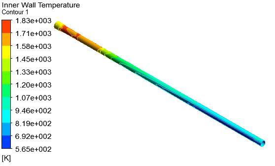
Figure 12.
Temperature distribution of inner wall surface of 2T magnetic field applied along z axis
Figure 13
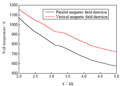
Figure 13.
Temperature curve of inner wall
4. Experimental Study on Heat Transfer Characteristics of Conductive Gas in Vertical Magnetic Field
4.1. Establishment of Magnetic Controlled Plasma Test System
Dielectric barrier discharge (DBD) is a kind of gas discharge with insulating dielectric insertion discharge space [16]. The advantage of this kind of discharge plasma is that it can form a large volume of plasma discharge region, and the discharge phenomenon is stable and uniform. Therefore, dielectric barrier discharge is used to ionize high temperature gas to produce conducting gas.
Figure 14 is the schematic diagram of test system, this test system consists of a plasma reactor, high temperature gas generator, magnetic field generator, temperature measuring device, and test rig.
Figure 14
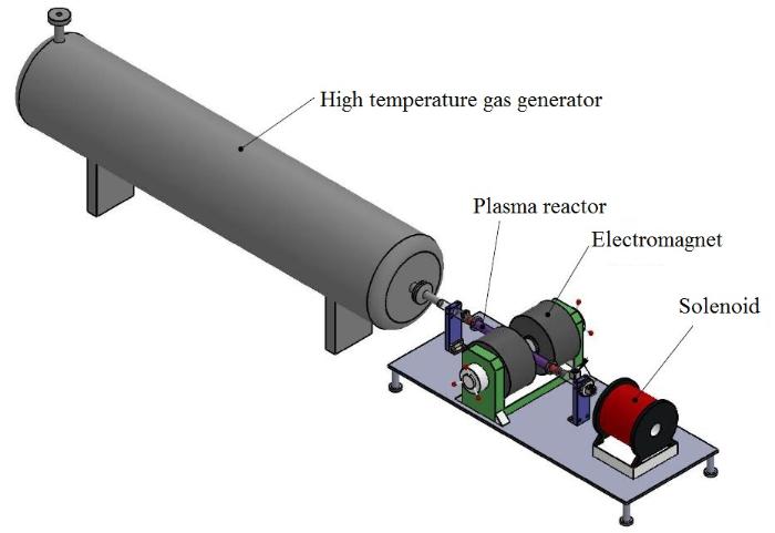
Figure 14.
Schematic diagram of test system
The plasma reactor [17] adopts a coaxial tube structure, and the insulating medium is a quartz tube with the size of Ф30×1000mm. The internal electrode is fixed on the center of the reactor with tungsten wire as the high pressure electrode. The external electrode is made of dense steel wire mesh tightly surrounding the outer wall of the dielectric tube and used as the grounding electrode. When the high frequency power supply is used, the velocity and direction of electron motion change due to the periodic variation of applied voltage, so the number of collisions between electrons and gas atoms is greatly increased. The ionization ability of electrons is also greatly improved. Therefore, we use a 20000Hz high frequency power source as a plasma generator. The schematic diagram of dielectric barrier plasma reactor is shown in Figure 15.
Figure 15
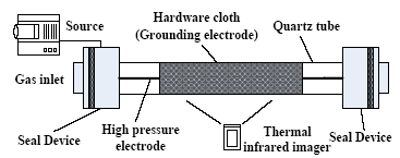
Figure 15.
Schematic diagram of dielectric barrier plasma reactor
The high temperature gas generator can provide heat input condition for the plasma reactor. It is used to simulate high temperature gas produced by combustion. Using a WD-100 type electromagnet of Beijing Bolanton electromagnetic company to apply a uniform vertical magnetic field on the outer wall of the quartz tube, when the current is 7.5A and the distance between the poles is 40mm, the intensity of the central magnetic field in the channel is 0.5T. The physical diagram of the test system is shown in Figure 16.
Figure 16
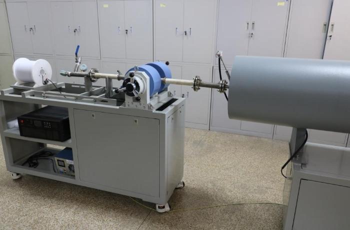
Figure 16.
Physical diagram of test system
4.2. Analysis of Results
In order to ensure the accuracy of temperature measurement, a non-contact infrared thermal imager is used to measure the temperature of the outer wall of quartz tube. Itobtains the temperature distribution of the object surface by receiving the infrared radiation of the measured object. Figure 17 shows a real-time display of the outer wall temperature of the quartz tube measured by the infrared thermal imager, in which the blue box is the temperature analysis area. The thermal imager automatically records and calculates the maximum temperature and average temperature in the area.
Figure 17
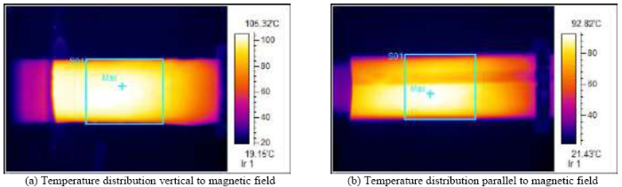
Figure 17.
Temperature distribution of quartz tube
Figure 18 shows the maximum temperature variation curve of the outer wall of the quartz tube in the working system of 100s. From the graph, we can see that after adding a magnetic field, the temperature of the outer wall is slightly lower than that without a magnetic field. The wall temperature in the parallel direction of the magnetic field is 92.82℃, while that in the vertical direction of the magnetic field is higher; the maximum value is 105.32℃. This is consistent with the temperature distribution of the simulation results. The wall temperature in the vertical magnetic field is higher than that in the parallel direction.
Figure 18
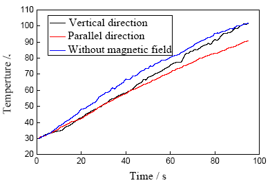
Figure 18.
Temperature curve of quartz tube
In order to analyze the effect of magnetic field intensity on the heat transfer characteristics of plasma, the working current of the electromagnet was adjusted to 0 ~ 8A respectively, and the corresponding central magnetic field intensity of the electromagnet was 0 ~ 0.5T respectively. Table 1 shows the wall temperature of the corundum tube measured by a thermocouple at different magnetic field intensities.
Table 1. Temperature of tube wall at different magnetic field intensity
| Time | Temperature/℃ | ||
|---|---|---|---|
| B=0T | B=0.25T | B=0.5T | |
| 0s | 30.0 | 30.0 | 30.0 |
| 20s | 48.3 | 46.9 | 43.9 |
| 40s | 67.0 | 63.5 | 58.4 |
| 60s | 80.5 | 75.6 | 73.6 |
| 80s | 95.4 | 91.5 | 86.9 |
It can be seen from Table 1 that the wall temperature decreases with an increase in magnetic field intensity, which indicates that the magnetic field perpendicular to the flow direction of the conductive gas can change its flow field structure and effectively reduce its heat transfer ability.
5. Conclusions
In this paper, the turbulent dissipation model of conductive gas in the cylinder is constructed, and the effect of vertical magnetic field on the heat transfer characteristics of the conducting gas in the cylinder is analyzed. The results of the model are verified by experiments. The conclusions are as follows:
$\cdot$ The magnetic field vertical to the flow direction can effectively reduce the turbulent kinetic energy of the conductive gas and weaken the heat transfer capacity of the conductive gas. The flow distribution has anisotropic characteristics.
$\cdot$ When the vertical magnetic field is applied, the radial diffusion of the charged particles can be restricted, and the heat transfer of the conductive gas to the wall of the cylinder is reduced.
$\cdot$ The heat transfer characteristic of the high temperature conductive gas is related to the direction of application of the magnetic field, and the wall temperature in the vertical magnetic field is higher than that in the parallel direction.
Acknowledgements
This work is supported by the National Basic Scientific Research Project of China.
Reference
Extended Magneto Hydrodynamic Plasma Jets with External Magnetic Fields
,”
DOI:10.1109/TPS.2016.2530634
URL
[Cited within: 1]

In this paper, collimated plasma jets form from Joule heating and ablation of a radial foil (Al 15- m-thin disk) using a pulsed power generator (Cornell Beam Research Accelerator) with 1-MA peak current and 100-ns rise time. Plasma dynamics of the jet are diagnosed with and without an applied uniform external magnetic field (~1-T axial Bz produced from a pulsed Helmholtz coil) and under a change of current polarity, which corresponds to current moving either radially inward or outward from the foil's central axis. Experimental results are compared with predictions made by numerical simulations (Plasma as an Extended-MHD Relaxation System using an Efficient Upwind Scheme). The influence of the Hall effect on the jet development is observed under opposite current polarities.
Studies on MHD Interaction in Hypervelocity Ionized Air Flow over Aero-Surfaces
,” in
Design of a MT-DBDReactor for H2S Control
,”
DOI:10.1088/2058-6272/aa57e8
URL
[Cited within: 1]

This study aimed to discuss the removal of hydrogen sulfide(H_2S) with non-thermal plasma produced by a multilayer tubular dielectric barrier discharge reactor,which is useful in the field of plasma environmental applications.We explored the influence of various factors upon H_2S removal efficiency( _(H_2S))and energy yield(Ey),such as specific energy density(SED),initial concentration,gas flow velocity and the reactor configuration.The study showed that we can achieve _(H_2S) of 91%and the best Ey of 3100 mg kWh~(-1) when we set the SED,gas flow velocity,initial H_2S concentration and layers of quartz tubes at 33.2 J1~(-1),8.0 m s~(-1),30 mg m~(-3) and five layers,correspondingly.The average rate constant for the decomposition of hydrogen sulfide was 0.206 g m~(-3)s~(-1).In addition,we also presented the optimized working conditions,byproduct analysis and decomposition mechanism.
Performance Analyses of MHD Thruster Using CAE Tools
,”
Computations of Turbulent Magneto HydrodynamicFlows
,” in
DOI:10.2514/6.2002-2141
URL
[Cited within: 1]
ABSTRACT Turbulent magnetohydrodynamic flows are numerically investigated. The Baldwin-Lomax algebraic model and the Baseline two-equation model that evaluate the turbulent viscosity are modified in the presence of a magnetic field and calibrated for the
Effect of Electron Temperature on the Characteristics of Plasma Sheath in Hall Thruster
,”
Electrostatic Manipulation of a Hypersonic Plasma Layer-Images of the Two-Dimensional Sheath
,”
DOI:10.1109/TPS.2008.926968
URL
[Cited within: 1]
The sheath shape in a cylindrical electrode system is simulated by using a 2-D fluid model. The cylindrical electrode system introduces an electron-depleted region, i.e., a sheath. The generated sheath may suggest a possible approach to the communication blackout problem that occurs for a reentry vehicle, in hypersonic flight or during laser interaction with a target. This approach can work if the electron-depleted sheath region extends over the vehicle surface up to the peak of the plasma density which is typically few centimeters. In addition, for efficient communication, the sheath region should be larger than the physical size of an antenna. To estimate the size of the plasma sheath, the electron number density and the potential distribution near the cylindrically shaped electrodes are presented, and the plasma sheath is indicated.
Investigation of Plasma Detachment from a Magnetic Nozzle in the Plume of the VX-200 Magnetoplasma Thruster
,”
DOI:10.1109/tps.2014.2321257
URL
[Cited within: 1]
Understanding the physics involved in plasma detachment from magnetic nozzles is well theorized, but lacking in large scale experimental support. We have undertaken an experiment using the 150-m(3) variable specific impulse magnetoplasma rocket test facility and VX-200 thruster seeking evidence that detachment occurs and an understanding of the physical processes involved. It was found that the plasma jet in this experiment does indeed detach from the applied magnetic nozzle (peak field similar to 2 T) in a two part process. The first part involves the ions beginning to deviate from the nozzle field 0.8-m downstream of the nozzle throat. This separation location is consistent with a loss of adiabaticity where the ratio of the ion Larmor radius to the magnetic field scale length (r(Li)vertical bar del B vertical bar/B) becomes of order unity and conservation of the magnetic moment breaks down. Downstream of this separation region, the dynamics of the unmagnetized ions and magnetized electrons, along with the ion momentum, affect the plume trajectory. The second part of the process involves the formation of plasma turbulence in the form of high-frequency electric fields. The ion and electron responses to these electric fields depend upon ion momentum, magnetic field line curvature, magnetic field strength, angle between the particle trajectories, and the effective momentum transfer time. In stronger magnetic field regions of the nozzle, the detached ion trajectories are affected such that the unmagnetized ions begin to flare radially outward. Further downstream as the magnetic field weakens, for higher ion momentum and along the edge of the plume, the fluctuating electric field enables anomalous cross-field electron transport to become more dominant. This cross-field transport occurs until the electric fields dissipate similar to 2-m downstream of the nozzle throat and the ion trajectories become ballistic. This transition to ballistic flow correlates well with the sub-to-super Alfvenic flow transition (beta(k)). There was no significant change observed to the applied magnetic field.
Plasmas in MHD Power Generation
,”
DOI:10.1109/27.125040
URL
[Cited within: 1]
The plasma found in a magnetohydrodynamic (MHD) generator is discussed. An MHD generator is an expansion engine. It delivers electric rather than mechanical power and there are virtually no upper limits to the temperature it can tolerate, the rapidity of its response, or the power a single unit can be designed to deliver. The behavior of the plasma is uncomplicated compared to that encountered in some other devices, and yet complex, because of the precision with which one needs to know it. The topics included are: generator configurations; electron density; electron mobility; mixture rules; the Hall effect; uniformity; two-temperature plasma; ionization growth at a channel inlet; ionization instability; high enthalpy extraction experiments; segmenting; electrode voltage drop; arcs and electrodes; electrical effects of slag; current control; and waves
Experiential Study on Propellant Driven Magnetohy Dynamic Generator
,”
Analysis of Rifling Land Damage Mechanism of Gun Barrel
,”
Influence of Magnetically Controlled Plasma on the Flow and Heat Transfer in a Circular Tube
,”
Numerical Study of Acceleration Deceleration Control of Three-Dimensional Magnetohydrodynamic Flow in Channel
,”The mechanism of magnetohydrodynamic(MHD) control is demonstrated in the article.Based on small magnetic Reynolds number assumption,the performance of MHD accelerator under various MHD parameters as magnetic field and electric field is concluded by numerical simulation of flow field added with various electric and magnetic field conditions in 3D MHD channel.The prospect of the MHD accelerator is evaluated in the article.Result shows: with 6000V/m electric field and 0.92T magnetic field added,the outlet velocity is accelerated by 13.46%,and it is decelerated by 16.35% when 0.92T magnetic field added.
Velocity Fluctuations in the Near-Wall Region of the Turbulent Channel Flow
,”
Temperature Simulation Calculation and Analysis of Influential Factors of a Certain Gun Barrel
,”During the process of gun firing,the temperature in bore would rise because of periodical scouring from high temperature gas,so there were more thermal security problems when modular charge with energy-filled material as the main ingredients was loaded into chamber. A description was made of the heat transfer law of gun barrel for a howitzer during continuous firing by using one-dimensional twophase flow interior ballistic model and one-dimensional axial symmetry heat transfer model. Through a comparison of calculated results and test results,the accuracy of the model was verified. On the basis of this model,temperature field of continuous firing 20 rounds was simulated,with temperature distribution law at different positions of inner and outer gun barrel achieved and the effect of different environment temperatures,firing conditions and thickness of barrel on temperature variation law of barrel analyzed. The results show that firing conditions had a greater influence on temperature radial distribution law in chamber,but environment temperature and thickness of barrel had little influence on it.Environment temperature and firing conditions had a greater influence on firing round that the highest temperature in chamber rise to alarm temperature,but thickness of barrel had little influence on it.Calculation results of this text provided reference for the analysis of charge firing thermal safety,thermal ablation and life of barrel.
