


1. Introduction
Wind energy is a very important renewable energy that plays a key role in wind power generation. Compared with other energy resources, wind energy has obvious advantages and prominent limitations. Wind energy is a renewable and exhaustless energy resource. The development and utilization of wind energy does not pollute the environment and has little influence on the ecological balance. Converting wind energy into mechanical energy is relatively simple and easy to realize. Due to the change of air flow, the wind becomes very unstable and fluctuating. Although wind energy is generally a rich resource, its distribution in time and space is very uneven. Because the wind energy density is very small, it is difficult to capture wind energy in practice. With the development of wind energy technology, the reliability design and service life of wind turbine are increasingly concerned by engineers. The wind turbine blades whose costs account for about 1/3 of the wind turbine are the main components for capturing wind energy. The aerodynamic load will directly affect the stability of blades and the conversion coefficient of wind energy. Because of the elasticity characteristic of the wind turbine blade, it is easily caused by random wind load in complex running environments, and thus the dynamic response characteristics of blades become more complex. The aerodynamic load of blades is the main factor that affects the stability of blades and the coefficient of wind energy conversion, so it is necessary to analyze and study the aerodynamic load of wind turbine blades.
According to the national effective wind energy density and annual cumulative hours of wind speed greater than or equal to 3m per year, we can sum up the provinces with abundant wind energy resources in China. Because of their unique geographical locations, the areas with abundant wind energy resources are mainly located in northwest China and some coastal areas.
Some provinces with abundant wind energy resources and their wind energy resources in China are shown in Table 1.
Table 1. The provinces with abundant wind energy resources and its wind energy resources in China
| Province | Wind energy resources(MW) |
|---|---|
| Inner Mongolia | 61780 |
| Xinjiang | 34330 |
| Heilongjiang | 17230 |
| Gansu | 11430 |
| Jilin | 6380 |
| Hebei | 6120 |
| Liaoning | 6060 |
| Shandong | 3940 |
| Jiangxi | 2930 |
| Jiangsu | 2380 |
| Guangdong | 1950 |
| Zhejiang | 1640 |
| Fujian | 1370 |
| Hainan | 640 |
2. Mathematical Modeling
In the process of wind turbine design, the design of wind speed directly affects the size and cost of wind turbines and isa very important parameter [1-2]. The size of the wind usually refers to the size of the wind speed, which indicates the distance of the air flowing in the unit time. Wind speed distribution is an important measure of the distribution characteristics of wind energy. Swedish physicist Weibull proposed the Weibull distribution model in 1939, and then the Weibull distribution was used to describe the frequency distribution characteristics of wind speed. Its curve is simple, and the effect of fitting the actual wind speed is good. The variation of average wind speed is random, but its distribution has certain statistical regularity. The statistical distribution of wind speed can be described by using a probability distribution function and probability density function in probability theory and mathematical statistics. The probability distribution density function is obtained as follows:
Here,$v$ is the wind speed, $C$ is the Weibull distribution dimension parameter, and $K$ is the Weibull distribution shape parameter. When $C$=1, it is called the standard Weibull distribution. The change of shape parameters has great influence on the form of distribution curve. When 0<$k$<1, the mode of distributions is 0 and the distribution density is a minus function of $v$; when $k$=1, it is an exponential distribution;when $k$=2, it becomes the Rayleigh distribution; and when k=3.5, the Weibull distribution is actually very close to the normal distribution.
After the probability distribution density function is integrated, the empirical distribution function is obtained as follows:
The Weibull distribution model can be used to deal with wind speed data to obtain the probability of wind velocity distribution in a region, and thus it can also make better plans for the wind turbine construction environment [3].
The blade is the primary carrier for the power input of wind turbine and determines the overall performance and utilization coefficient of the wind turbine. During the operation of the wind turbine, the blade must bear a wind load and centrifugal force. Because the blade is slender, heavy, and large, it is affected by the constantly changing flowing air, and its bending torque is quite complicated.
The blade design includes two parts: aerodynamic design and structural design. The aerodynamic design takes into account the rated wind speed, utilization coefficient of wind energy,shape size, and aerodynamic load [4].The blade is a main component with aerodynamic characteristics. It can receive wind energy to rotate the wind turbine around its axis and generate lift during operation.The material used to make the blades must be high strength and low quality, and its physical and chemical properties are stable under bad weather conditions [5].The blades are often made of aluminum alloy, stainless steel, glass fiber resin matrix composite, carbon fiber resin matrix composite, wood, and so on.Considering the different materials used in the blade structure and the complicated operating environment [6], the thermal expansion of the blade must be considered in order to avoid the additional stress caused by temperature changes. In addition, during processing and design, designers should pay attention to the sealing and lightning protection of the blades. The wind turbine blade structure is shown in Figure 1.
Figure 1
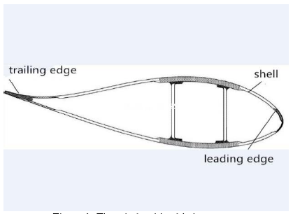
Figure 1.
The wind turbine blade structure
In order to increase the strength and stiffness of the blade, a web structure should be bonded between the two shells. In order to let the trailing edge stiffer, the upper part of the blade and the lower part of the blade can also be glued to the foam plate before assembly.Wind turbine performance mainly includes power characteristics, torque characteristics, and axial force characteristics in Table 2, which all depend on the aerodynamic characteristics of wind turbine blades [7].
Table 2. Blade description
| r(m) | Torsion angle (o) | Chord length (m) |
|---|---|---|
| 4.5 | 20.00 | 1.630 |
| 5.5 | 16.30 | 1.597 |
| 6.5 | 13.00 | 1.540 |
| 7.5 | 10.05 | 1.481 |
| 8.5 | 7.45 | 1.420 |
| 9.5 | 5.85 | 1.356 |
| 10.5 | 4.85 | 1.294 |
| 11.5 | 4.00 | 1.229 |
| 12.5 | 3.15 | 1.163 |
| 13.5 | 2.60 | 1.095 |
| 14.5 | 2.02 | 1.026 |
| 15.5 | 1.36 | 0.955 |
| 16.5 | 0.77 | 0.881 |
| 17.5 | 0.33 | 0.806 |
| 18.5 | 0.14 | 0.705 |
| 19.5 | 0.05 | 0.545 |
| 20.3 | 0.02 | 0.265 |
In 1989, Froude proposed the blade element theory. In 1892, Drzewiecki made significant improvements to the blade element theory [8]. He introduced a method to analyze the force on the blade from the flow near the blade element, which can be better applied to the design of wind turbine blade.
In this paper, the blade element theory simplifies the three-dimensional flow of airflow through the wind turbine into two-dimensional flow on each independent blade element, which do not interfere with each other [9]. It ignores the influence of the airflow between the blades, thereby ignoring the energy exchange between the adjacent blades because of the rotation of the wind turbine, gravity, centrifugal force, inertial force, and so on [10]. Therefore, the force and torque acting on each blade are decided only by the profile of the blade.The velocity and force of blade flow is shown in Figure 2.
Figure 2
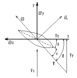
Figure 2.
The velocity and force of blade flow
Here,$\theta $ means the installation angle, $\alpha $ means the attack angle, $\phi $ means the relative wind angle,$\text{d}L$ means the lift of the blade profile section, $\text{d}D$ means the drag of blade profile section, $\omega $ means the angular velocity of the wind turbine, ${{V}_{s}}$ means the wind speed, $W$ means the relative wind speed, $\text{d}{{F}_{x}}$ means the normal force, and$\text{d}{{F}_{y}}$ means the tangential force. There are two airflow velocity components in the blade element:${{V}_{x}}$ means the component that is perpendicular to the plane of the wind turbine, and ${{V}_{y}}$ means the component that is parallel to the plane of the wind turbine. ${{V}_{x}}$ and ${{V}_{y}}$compose the triangle of the speed.
The load of each section of the blade is mainly used to calculate blade strength, including ultimate strength and fatigue strength. Here, the load of each section of the blade is mainly used to calculate the force and torque of the blade.
The velocity relationship is obtained below:
When the air flow acts on the aerofoil, the pressure generated on the lower surface of the aerofoil is higher, while the pressure generated on the upper surface of the aerofoil is lower.Due to the pressure difference between the upper and lower surfaces, drag and lift are only generated on the aerofoil during air flow through the blade [11].The force acting in the opposite direction along the air flow is called drag because it prevents the blade from moving forward. Another force that is perpendicular to the direction of air flow is called lift.
The normal force $\text{d}{{F}_{x}}$ and tangential force $\text{d}{{F}_{y}}$ are composed of the components of the lifting $\text{d}L$ and the drag $\text{d}D$ respectively:
Here, $\alpha$ means the axial induction factor and ${\alpha }'$ means the tangential induction factor.
According to the airfoil theory, the micro-element lift and resistance of the blade element are expressed respectively as follows:
Here, $\rho$ is the density, $C$ is the chord length,$r$ is the radius, ${{C}_{L}}$ is the lift coefficient, and ${{C}_{D}}$ is the drag coefficient.
When the micro-element lift and drag on the blade element are substituted into the formulas of normal force and tangential force respectively, the result is expressed as follows:
The torque and axial force of the wind turbine can be obtained respectively as follows:
Here,$B$ is the blade number.
The torque and axial force of the blade are obtained respectively by using the momentum theory.
Here,$U$ is the inflow velocity.
When the two expressions of $\text{d}M$ and $\text{d}Q$ are equal, it can be obtained below:
Here, $\sigma =BC/2\pi r$.
The inflow angle of wind at the blade tip is not zero, so the force and load at blade tip are not zero when the blade element theory is used to calculate the thrust and power of wind turbine [12-14]. At the tip of the blade, the air flow is transferred from the pressure of the blade to the suction surface, which results in a practically zero load at the tip of the blade.
We need to introduce Planck loss factor $\xi$ to correct the calculated axial induction factor and tangential induction factor.
Here, ε means the influence coefficient of the tip and $R$ means the radius of the wind turbine.
The load calculated by the blade element theory is not zero. In practice, the load on the blade tip of the wind turbine blade tends to zero. This requires a correction of the mathematical model of the load and torque. When the blade tip wind speed loss and the blade tip structure are considered, the Planck loss factor is introduced.
It can be obtained below:
The modified axial induction factor and the tangential induction factor can be substituted into the torque and axial force calculation formulas of the blade to obtain a more optimized algorithm. In subsequent calculations, a more accurate load can be obtained.
3. Example Calculation and Model Solution
Some parameters of the blades are shown below:
Table 3. Basic parameters of blades
| Power | P=1.5MW |
|---|---|
| The rated wind speed | V=10m/s |
| Aerofoil | NACA4412 series |
| Blade length | R=3.2m |
| Blade number | B=3 |
| Rated speed | n=20r/min |
| Cut - in wind speed | V1=4m/s |
| Cut - out wind speed | V2=25m/s |
| Air density | 1.225kg/m3 |
The diameter of the wind turbine indicates the extent to which the unit can obtain the energy contained in the wind.
The rated power is the power of the generator nameplate matched with the unit. The definition of rated power is the maximum continuous output electric power by the design of the wind turbine under normal working conditions [17].
The following table is obtained through a wind tunnel experiment:
Table 4. Experimental load data
| No. | The wind speed (m/s) | Blade loading (KN) |
|---|---|---|
| 1 | 5 | 40.44 |
| 2 | 10 | 241.56 |
| 3 | 20 | 220.23 |
| 4 | 30 | 194.98 |
| 5 | 40 | 162.45 |
The most typical low-speed aerofoil is NACA, which was proposed by NASA in the late 1930s and early 1940s.Among the existing aerofoil data, NACA series aerofoil data are quite complete, and most of the wind turbine blades still use NACA series aerofoil. The NACA aerofoil has the best performance in general and has good insensitivity to the surface roughness, so it has been widely used in all kinds of horizontal axis wind turbines.
When the blade NACA4412 series parameters are substituted into mathematical model formula (13) in the MATLAB software, the calculated data is obtained.Figure 3 is obtained by comparing the calculated data with the experimental data.Figure 3 shows that the aerodynamic loads of blades are influenced by wind speed when axial induction factor ${\alpha}$ and tangential induction factor ${\alpha }'$ do not introduce the Planck coefficient (the comparison of calculated loads and experimental loads before correction is not performed).
Figure 3
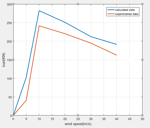
Figure 3.
Comparison of calculation load and experimental load
When the Planck coefficient is introduced, the axial induction factor $\alpha$ and the tangential induction factor ${\alpha}'$ are modified simultaneously. The axial induction factor $\alpha$ and the tangential induction factor ${\alpha}'$ are substituted into formulas (12) and (13) respectively, and the formulas are modified. Then, the MATLAB software is used to calculate the load of the blade.Figure 4 is obtained by comparing the calculated data with the experimental data.
Figure 4
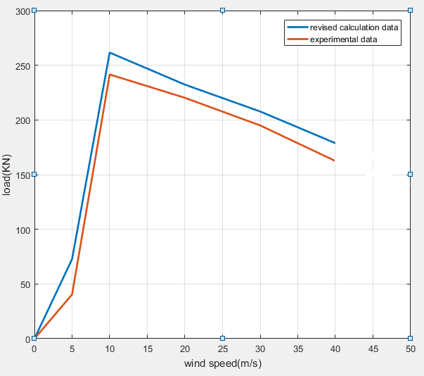
Figure 4.
Comparison of calculated load and experimental load after modification
For the NACA4412 series of blades, we can see that the calculated load in Figure 4 is consistent with the general trend of the experimental load. The data obtained by the modified algorithm is closer to the experimental data, and the comparison error is less than 10%. Through the study of experimental data and calculation data, it can be found that wind speed has the largest impact on load when the wind speed is 10m/s. It is advantageous to some performance of the wind turbine, and the increase in lift will be good for wind turbine power [18]. It is necessary to strengthen the root of its blade, because the root avoids excessive stress from breaking or brittle. This needs to be taken into consideration according to the wind turbine blade structure and materials [19]. The improved algorithm is very significant to the load calculation of the wind turbine.
The following table is obtained through a wind tunnel experiment:
Table 5. Experimental torque data
| No. | Thewind speed (m/s) | The torque of the blade (KN·m) |
|---|---|---|
| 1 | 5 | 170.26 |
| 2 | 10 | 732.12 |
| 3 | 20 | 645.17 |
| 4 | 30 | 601.57 |
| 5 | 40 | 565.28 |
The experimental torque data is compared with the calculated torque data when the axial induction factor $\alpha$ and the tangential induction factor ${\alpha}'$ are not modified in Figure 5. It can be found that the difference between the torque and the experimental torque is close to 100KN·m in the range of the wind speed of 10 ~ 20m/s. The error is about 1/7, so this calculation is not ideal and needs to be modified.
Figure 5
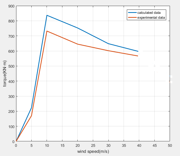
Figure 5.
Comparison of calculation torque and experimental torque
A better algorithm can be obtainedwhen the axial induction factor $\alpha$ and the tangential induction factor ${\alpha }'$ are modified by introducing the Planck coefficient$\xi $. The axial induction factor $\alpha$ and the tangential induction factor ${\alpha }'$ are substituted into the infinitesimal formula, which calculates the torque, and $\alpha $modified formula is obtained. Then, the MATLAB software is used to calculate the torque of the blade.Figure 6 is obtained by comparing the calculated data with the experimental data.
Figure 6
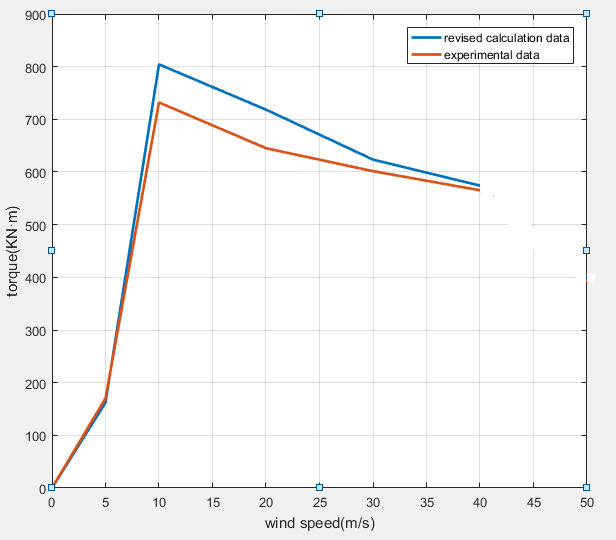
Figure 6.
Comparison of calculated torque and experimental torque after modification
It can be seen that difference of the maximum torque between the calculated data and the experimental data is not more than 70kN·m. The error is reduced to 1/10 in the same wind speed section as Figure 5. It is more similar to the actual situation, and the data calculated by the improved algorithm is closer to the experimental data. It can be considered that the algorithm is better than the algorithm that does not introduce the Planck coefficient $\xi $, and the algorithm is closer to the actual wind turbine blade [20-21]. This provides a more reliable way to study the torque of wind turbine blades in China.
The relationship between wind output powerand wind speed is as follows:
Here, $P$ means the output power, ${{C}_{P}}$ means the utilization coefficient of wind energy, ${{v}_{0}}$ means the actual wind speed,and $A$ means the cross-sectional area swept by the wind turbine.
It can be seen from the figure that when ${{v}_{0}}$ is 10m/s, the power generation capacity of wind turbines is the largest and the utilization coefficient of wind energy is maximized.If the wind speed is too low, the wind energy utilization rate of the wind turbine will not reach the maximum [22]. If the wind speed is too high, the utilization coefficient of wind energy will start to play a major role and will become smaller at the same time, which will also lead to a decrease in the output power of wind turbines [23]. The relationship between output power and speed of wind turbine is shown in Figure 7.
Figure 7
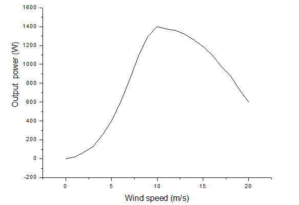
Figure 7.
The relationship between output power and speed of wind turbine
The utilization coefficient of wind energy is related to the axial induction factor as follows:
Table 6. The function relation between utilization coefficient of wind energy and axial induction factor
| α | Cp |
|---|---|
| 0.0 | 0.000 |
| 0.1 | 0.324 |
| 0.2 | 0.512 |
| 0.3 | 0.588 |
| 0.4 | 0.576 |
| 0.5 | 0.500 |
| 0.6 | 0.384 |
| 0.7 | 0.252 |
| 0.8 | 0.128 |
| 0.9 | 0.036 |
| 1.0 | 0.000 |
According to the above table, ${{C}_{P}}$ is also related to the axial induction factor.The table above lists ${{C}_{P}}$ within the range of 0.1 <$\alpha $< 1.0. When 0.1 <$\alpha $< 0.3, ${{C}_{P}}$ will increase; when 0.3 <$\alpha $< 1.0, ${{C}_{P}}$will decrease; when $\alpha $ = 0.1 and $\alpha $ = 1.0, ${{C}_{P}}$ is 0; when $\alpha $ = 0.3, ${{C}_{P}}$ is the largest.
Figure 8 shows the curve of ${{C}_{P}}$ under different drift angles of wind turbines.It can be seen from the figure that ${{C}_{P}}$ decreases when there is a drift angle, because the inflow velocity perpendicular to the wind turbine decreases.When the drift angle is 15°, ${{C}_{P}}$ decreases by about 10%.When the drift angle increases, ${{C}_{P}}$ decreases [24]. Therefore, generally horizontal axis wind turbines are equipped with yaw mechanisms to adjust the direction when the wind direction changes greatly.In order to avoid the influence of the alternating load on the structural fatigue strength of the large wind turbine[25], the adjustment of the direction adjusting mechanism will begin when the change of the wind direction is more than 15°.
Figure 8
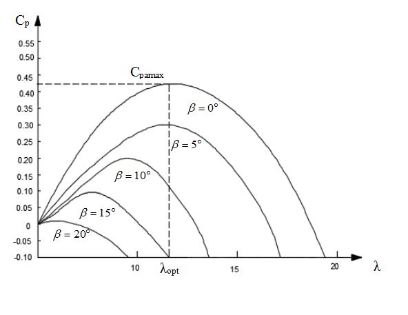
Figure 8.
Utilization coefficient of wind energy at different drift angles of wind turbines
The main parameters influencing ${{C}_{P}}$ include wind turbine structure [26], number of wind turbine blades, blade chord length distribution, aerodynamic performance, and blade twist angle.When the wind turbine is low in solidity, ${{C}_{P}}$ is kept high in a wide range of blade tip speed ratios. When the wind turbine is high in solidity, a high ${{C}_{P}}$ can only be maintained within a narrow blade tip speed ratio range.As the solidity increases, the tip speed ratio corresponding to the maximum ${{C}_{P}}$ of the wind turbine will decrease [27]. When the wind turbine is too high in solidity,the maximum ${{C}_{P}}$ ofthe wind turbine will decrease.The best wind turbine is a two-blade or three-blade wind turbine.Although the variation ${{C}_{P}}$ of two-blade wind turbines is smaller than that of three-blade wind turbines in the wide blade tip speed ratio range, the maximum ${{C}_{P}}$ of three-blade wind turbines is higher than that of two-blade ones.As a result, three-bladed wind turbines may have higher annual output power.
The so-called optimal design is that a wind turbine with a given turbine diameter can generate as much power as possible every year.Annual power generation must take into account the wind speed distribution at the installation site as well as some important parameters of the wind turbine.The blade element theory combined with the optimal algorithm can optimize the geometric shape of the blade. The ultimate load also needs to be verified later.
4. Conclusions
In this paper, the load and torque of the two most important parameters of the 1.5MW NACA4412 series wind turbine blade are analyzed. The original algorithm is modified. Through the Weibull wind speed distribution model, the load and torque of wind turbine blades are calculated by the modified algorithm. When the wind speed is at 10m/s, the wind speed has the greatest influence on the load and torque. Then, the calculated error is compared, and the load and torque that are calculated by the optimization algorithm are closer to the actual wind condition. The paper provides a new idea for the study of aerodynamic loads of wind turbine blades. A more reliable model is obtained by calculation and comparison, which is significant to the follow-up study of wind turbines.
Acknowledgements
This paper is supported by the 2018 Inner Mongolia Autonomous Region Science & Technology Plan Project.
Reference
Aerodynamics Performance of Continuously Variable Speed Horizontal Axis Wind Turbine with Optimal Blades
,”
DOI:10.1016/j.energy.2014.09.048
URL
[Cited within: 1]

61Aerodynamic design of optimum rotor for variable speed HAWTs (horizontal axis wind turbines) is considered here.61The BEM (blade element momentum) theory re-visited and extended.61A new quadratic mathematical solution is obtained for angular induction factor.61Variable speed rotor has superiority particularly in low speed ratios.61The power performance of variable speed rotor is considerably high.
Aero Elastic Design of Large Wind Turbine Blades Considering Damage Tolerance
,”
Analysis of Transient Response of Wind Turbine Blade based Timoshenko Beam
,”
Design and Optimization of Aerodynamic Shape and Operating Characteristics of Large Scale Wind Turbine Blade
,”
DOI:10.3901/JME.2015.17.138
URL
[Cited within: 1]

When designing the aerodynamic shape parameter of large scale wind turbine blade, both the aerodynamic shape parameter optimization and the operating characteristics should be considered because the operating characteristics are the control basis for wind turbines. A novel aerodynamic shape and operating characteristic optimization design method for the blade is proposed. The control equations of airfoil distribution, chord length distribution and twist angle distribution are constructed. The influences of various parameters on the wind rotor power are analyzed based on the blade element momentum theory(BEM). The optimization target is to reduce the rated wind speed while the rated power is constant. In the optimization process, the influence of the initial pitch angle is considered. Aiming at the optimized wind rotor, the relationship curve between the torque and the rotational speed is designed, the running characteristics are analyzed. Finally, the correctness of the design results is verified by using the computational fluid dynamics(CFD).
Investigation of Aerodynamic Performance and Wake of the Large Scale Wind Turbine in Complicated Conditions
,”
Aerodynamic Load Analysis of Offshore Wind Turbine Blades During Typhoon
,”The aerodynamic characteristics of offshore wind turbine blades during typhoon were investigated according tothe observation data of typhoon"Damrey"(2005,NO.0518)and the main design parameters of National RenewableEnergy Lab(NREL)5 MW wind turbine. Firstly,because the full observation data of typhoon was a long durationprocess with obvious variation characters of wind speed and wind direction,so one 3-hour representative truncatedtyphoon wind speed-wind direction time history was selected. Secondly,considering the main airfoil design parameters of5 MW wind turbine blades and the variable-speed and collective-pitch control system,the aerodynamic characteristics ofoffshore wind turbine blades during representative typhoon period were studied based on Blade Element Momentum(BEM)theory,and the numerical results was compared with the results of simplified method. The important effect of thetime lag of the variable-speed and collective-pitch control system on the blades aerodynamic loads during typhoon wasrevealed. Finally,the blade aerodynamic loads during typhoon for stopped wind turbine were further studied,and theactive blade parked strategy for typhoon event was suggested to reduce the blades aerodynamic loads and ensure thesafety of the key structures of wind turbine.
Optimization of Wind Turbine Thick Aerofoils Using Improved Multi-Objective Particle Swarm Algorithm
,”
DOI:10.3969/j.issn.1005-3026.2016.02.018
URL
[Cited within: 1]
Considering the lowstructural performance of wind turbine airfoils designed just with aerodynamic performance as an optimization objective,a newmulti-objective optimization method is proposed based on improved multi-objective particle swarm optimization, which balances aerodynamic and structural performance of airfoils. The airfoils with thickness of 40% are parametrically described using the wind turbine airfoil integrated theory. The optimization objectives are the maximum lift-drag ratio when designing attack angles and the maximum inertia moment about the chord axis,with such requirements as stalling characteristics,sensitivity to leading edge roughness and design lift at off-design condition considered together. The Pareto-optimal set of airfoils is obtained. The representative airfoils in the set outperform the airfoil( DU00- W2- 401) in terms of aerodynamic and structural performance.
Structural Optimization of Wind Turbine Rotor Blades by Multilevel Sectional/Multibody/3D-FEM Analysis
,”
DOI:10.1007/s11044-013-9394-3
URL
[Cited within: 1]
The present work describes a method for the structural optimization of wind turbine rotor blades for given prescribed aerodynamic shape. The proposed approach operates at various description levels producing cost-minimizing solutions that satisfy desired design constraints at the finest modeling level. At first, a “coarse”-level constrained design optimization is performed by using a 1D spatial geometrically exact beam model for aero-servo-elastic multibody analysis and load calculation, integrated with a 2D FEM cross sectional model for stress/strain analysis, and the evaluation of the 1D model fully-populated cross sectional stiffness matrices. Next, a “fine”-level 3D FEM model is used for the refinement of the coarse-level solution. Improved results obtained at the level of the 3D model are utilized at the following coarse-level iteration through a heuristic modification of the design constraints. In addition, a buckling analysis is performed at the fine description level, which in turn affects the nonstructural blade mass. The updated constraint bounds and mass make their effects felt at the next coarse-level constrained design optimization, thereby closing the loop between the coarse and fine description levels. The multilevel optimization procedure is implemented in a computer program and it is demonstrated on the design of a multi-MW horizontal axis wind turbine rotor blade.
Numerical Simulation for in-Cloud Icing of Three-Dimensional Wind Turbine Blades
,”
Dynamic Response of Flexible Wind Turbine Blade
,”
Impact for Blade Position on Aerodynamic Performance of Wind Turbine System under Stopped Status
,”
An Effective Method to Inspect Adhesive Quality of Wind Turbine Blades Using Transmission Thermography
,”
Mechanical Behaviour of Thick Structural Adhesives in Wind Turbine Blades under Multi-Axial Loading
,”
Structural Optimization Vertical-Axis Wind Turbines Composite Blades based on Finite Element Analysis and Genetic Algorithm
,”
Flow Field Simulation and Optimization Design of Concentrated Wind Energy Device
,”
Simulation and Experiment on Flow Field Characteristics of Concentrated Device of Concentrated Wind Energy Turbines in Wind Shear
,”
Dynamic Modelling and Constant Power Control of Wind Turbines with Trailing-Edge Flaps
,”
Analysis on the Influence of Dynamic Aerodynamic Loads and Component Vibration of Wind Turbine on Aero Elastic Characteristics
,”
Puncture Position on Wind Turbine Blades and Arc Path Evolution under Lightning Strikes
,”
Effects of Wind Shear on Aerodynamic Loads of Wind Turbines
,”
Genetic-Algorithm-based Optimal Apportionment of Reliability and Redundancy under Multiple Objectives
,”
Strategies Study Of Individual Variable Pitch Control for High-Power Wind Turbines in Full Load Cases
,”
Dynamic Loads Calculation of the Drive-Train of the Wind Turbines in Different Operation in Conditions
,”
Effect Analysis of Disturbance Airflow on Pneumatic Attack Angle of Darrius-Type Wind Turbine
,”
Wind-Included Vibration Response Analysis for a Large Wind Turbine Blade-Tower System based on Large Eddy Simulation
,”
Integrated Design of Aerodynamic and Structural Performance for Wind Turbine Dedicated Aerofoil
,”
Flow Field Simulation Verification and Flanged Structure Optimized Design of Concentrated Wind Energy Device Diffuser
,”
